


Galaxy A16F-R2422 Installation and Hardware Reference Manual
Introduction
1-14
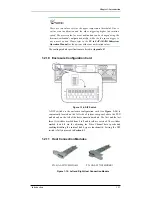
Two (2) host connection modules are installed above the PSUs and are
secured to the chassis by two (2) retention screws on the rear panel. Each
module has two (2) ports that accept SFP transceivers. The default
configurations do not include SFP transceivers on the FC ports. You can
order the field-replaceable unit, SFP tranceivers (GAL-9270CSFP4GA01)
from your subsystem vendor. These SFP tranceivers have been selected and
tested to provide the necessary reliability and performance.
When the host connection module is installed with SFP transceivers, that
will allow you to connect the A16F-R2422 to host computer(s), external
devices and daisy chain A16F-R2422 subsystems at transfer rates up to
2Gbit per second.
All host connection modules come with bypass circuits and are routed to
both controllers. The bypass circuits ensure loop integrity and allow you to
configure redundant paths to the host computers. For configurations
involving multi path, multi host computers, and cascading A16F-R2422, be
sure to properly set the DIP switches. For details of the hardware
configurations, please refer to
Chapter 4
.
One (1) LED per FC port indicates the connection status. The modules are
hot swappable and support online maintenance.
1.3 A16F-R2422 Monitoring
The RAID subsystem comes with a number of different monitoring methods
that provide you with continual updates on the status of the system and
individual components. The following monitoring features are included in
the subsystem.
1.3.1 I
2
C bus
The following A16F-R2422 elements are interfaced to the RAID controller
over a non-user-serviceable I
2
C bus:
•
PSUs
•
Cooling modules
•
Temperature sensors (for the temperature of the backplane board
and controller board)
1.3.2 LED
Indicators
The following active components come with LEDs to indicate the status of
the individual component:
•
LCD panel (3 LEDs)
•
Drive trays (2 LEDs on each tray)


