


Galaxy A16F-R2422 Installation and Hardware Reference Manual
Introduction
1-6
that might occur while removing or installing these modules. Each
component is further described below:
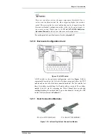
1.2.1 LCD
Panel
Figure 1-6: LCD Panel
PN: GAL-9273CHandLLCD
The LCD panel shown in
Figure 1-6
consists of a 16x2-character LCD
screen with push buttons and LED status indicators. The LCD front panel
provides full access to all RAID configuration settings and monitoring
functions. After powering up the subsystem, the initial screen will show the
subsystem model name. A different name may be assigned for the
subsystem, controller or different logical drive. This will enable easier
identification in a topology with numerous arrays.
1.2.2 Drive
Trays
Figure 1-7: Drive Tray Front View
PN: GAL-9273A2DT2S1S
The A16F-R2422 subsystem comes with sixteen (16) drive trays (see
Figure 1-7
) designed to accommodate separately purchased, standard 1-inch
pitch, 3.5-inch SATA disk drives. The drive bays are easily accessible from
the front of the enclosure. Each drive tray is pre-installed with a MUX kit.
Two (2) LEDs on the front of the tray indicate the drive status. A key-lock
on each drive tray secures the hard drive in place, while an easily accessible
button ensures fast and efficient drive hot-swapping. Retention screw holes
are located on the sides of the drive tray. These holes are reserved for
securing hard drives to the tray.
WARNING!


