17
3. Installation & Operation
•
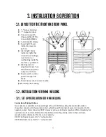
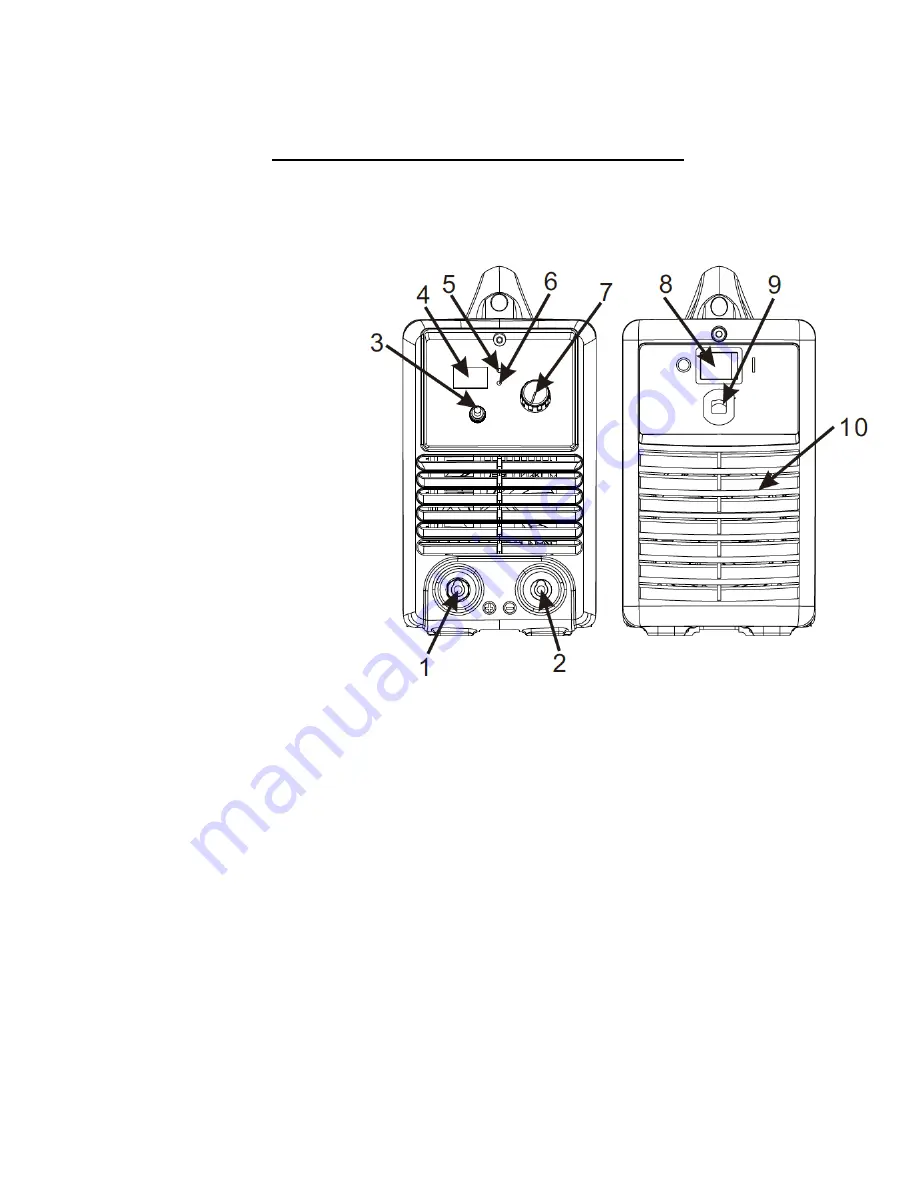
3.1. Layout for the front and rear panel
(1)
“+” Output terminal.
(2)
“-” Output terminal.
(3)
Conversion switch:
Choose (left) LIFT TIG;
choose (right) MMA.
(4)
Current digital display.
(5)
Power light: Power
indicator, power on
light on.
(6)
Alarm light: Alarm
indicator, lights that
occurred over voltage,
over current, or
overheating inside the
machine, is protected.
(7)
Welding current
adjustment knob: Turn
this knob to adjust the
output current size.
(8)
Power switch: control
power through and
break.
(9)
Power Access client: access to cable.
(10)
Fan: Help plant cooling.
•
3.2. Installation for MMA Welding
•
3.2.1. Set up installation for MMA Welding
Connection of Output Cables
Two sockets are available on this welding machine. For MMA welding the electrode holder is
shown be connected to the positive socket, while the earth lead (work piece) is connected to the
negative socket, this is known as DCEP. However various electrodes require a different polarity for
optimum results and careful attention should be paid to the polarity, refer to the electrode
manufacturers information for the correct polarity.
DCEP: Electrode connected to “+” output socket.
DCEN: Electrode connected to “-“ output socket.

