background image

36 


200

ARC


DV


STICK 

 TIG 


Summary of Contents for Ronch Weld 160ARC DV

Page 1: ...1 SERIES 160ARC DV 200ARC DV STICK TIG ...

Page 2: ...allation Operation 17 3 1 Layout for the Front and Rear Panel 17 3 2 Installation for MMA Welding 17 3 2 1 Setup Installation for MMA Welding 17 3 2 2 Operation for MMA Welding 19 3 2 3 MMA Welding 19 3 2 4 MMA Welding Fundamentals 21 3 2 5 MMA Welding TroubleShooting 23 3 3 Installation and Operation for TIG Welding 24 3 3 1 Set Up Installation for TIG Welding 24 3 3 2 Operation for TIG Welding 2...

Page 3: ...3 4 Maintenance Troubleshooting 30 4 1 Maintenance 30 4 2 Troubleshooting 32 4 3 List of Error Codes 34 4 4 Electrical Schematic Drawing 35 ...

Page 4: ...hers which could happen during the welding operation While seeing these symbols please remind yourself and others to be careful Only people who are trained professionally can install debug operate maintain and repair the welding equipment covered with this Operator s Manual During the welding operation non concerned people should NOT be around especially children After shutting off the machine pow...

Page 5: ...voltage between the two can be the total of the open circuit voltage of both welders When working above the floor level use a safety belt to protect yourself from a fall should you get an electric shock FUMES AND GASES CAN BE DANGEROUS Smoke and gas generated whilst welding or cutting can be harmful to people s health Welding produces fumes and gases Breathing these fumes and gases can be hazardou...

Page 6: ...ith suitable non flammable screening and or warn them not to watch the arc nor expose themselves to the arc rays or to hot spatter or metal SELF PROTECTION Keep all equipment safety guards covers and devices in position and in good repair Keep hands hair clothing and tools away from V belts gears fans and all other moving parts when starting operating or repairing equipment Do not put your hands n...

Page 7: ...xplosion even though they have been cleaned Vent hollow castings or containers before heating cutting or welding They may explode Sparks and spatter are thrown from the welding arc Wear oil free protective garments such as leather gloves heavy shirt cuff less trousers high shoes and a cap over your hair Wear earplugs when welding out of position or in confined places Always wear safety glasses wit...

Page 8: ...are held secure and upright to prevent tipping or falling over Never allow the welding electrode or earth clamp to touch the gas cylinder do not drape welding cables over the cylinder Never weld on a pressurised gas cylinder it will explode and kill you Open the cylinder valve slowly and turn your face away from the cylinder outlet valve and gas regulator Gas build up The build up of gas can cause...

Page 9: ...ith heart pacemaker should be away from the welding area Noise can damage hearing Noise from some processes or equipment can damage hearing You must protect your ears from loud noise to prevent permanent loss of hearing To protect your hearing from loud noise wear protective ear plugs and or ear muffs Protect others in the workplace Noise levels should be measured to be sure the decibels sound do ...

Page 10: ...e interference Accoring to the domestic and international standards the ambient devices electromagnetism situation and anti interference ability must be checked Safety device Power line Signal transmission line and Date transmission line Date processing equipment and telecommunication equipment Inspection and calibration device The effective measures avoid the problem of EMC a Power source Even th...

Page 11: ...ing label The device with a warning label Do not remove destroy or cover this label These warnings are intended to avoid incorrect device operations that could result in serious personal injury or property damage ...

Page 12: ...de sticking to the work piece Smoother welding and deeper penetration Anti sticking device to prevent overload and ease the electrode removal from the workpiece Protections Fully protected against over voltage under voltage and over heat Digital display Variable amperage control with digital meter for a simultaneous welding current display Weight Generator friendly Designed to work with diesel gen...

Page 13: ... Cooling AF Net Weight kg 4 0 Dimensions mm 290 135 280 Electrode Diameter ø1 6 ø4 0 Electrode Type 6013 7018 etc Note The above parameters are subject to change with future machine improvement Models Parameters ARC 160 LT DV ARC 180 LT DV Power Supply Voltage V 1 110V 10 1 220V 10 1 110V 10 1 220V 10 Frequency HZ 50 60 MMA TIG MMA TIG MMA TIG MMA TIG Rated input current A 51 33 5 34 23 51 33 5 40...

Page 14: ...5 0 Electrode Type 6013 7018 etc Note The above parameters are subject to change with future machine improvement 2 3 Brief Introduction ARC series of welding machines adopt the latest Pulse Width Modulation PWM technology and the Insulated Gate Bipolar Transistor IGBT power modules It uses switching frequencies in the 20KHz 50KHz ranges so as to replace the traditional line frequency transformer t...

Page 15: ...ous operation The frame is Stability of the machine which can keep working under high temperature and corrosion environment MMA Manual Metal Arc welding PWM Pulse Width Modulation IGBT Insulation Gate Bipolar Transistor TIG Tungsten Inert Gas welding 2 4 Duty cycle and Over heat The letter X stands for Duty Cycle which is defined as the portion of the time a welding machine can weld continuously w...

Page 16: ...elding current parameters can be adjusted continuously and steplessly to meet with the requirements of welding craft 2 6 Volt Ampere Characteristic ARC series of welding machines has excellent volt ampere characteristic Referring to the following graph In MMA welding the relation between the rated loading voltage U2 and welding current I2 is as follows When I2 600ª U2 20 0 04 I2 V When I2 600ª U2 ...

Page 17: ...d break 9 Power Access client access to cable 10 Fan Help plant cooling 3 2 Installation for MMA Welding 3 2 1 Set up installation for MMA Welding Connection of Output Cables Two sockets are available on this welding machine For MMA welding the electrode holder is shown be connected to the positive socket while the earth lead work piece is connected to the negative socket this is known as DCEP How...

Page 18: ...ble connected to the appropriate position not to pick the wrong voltage 5 With the corresponding input power supply terminal or socket good contact and prevent oxidation 6 With a multi meter measure the input voltage is within the fluctuation range 7 The power ground is well grounded 3 2 2 Operation for MMA Welding 1 According to the above method to install is correct turn the power switch so that...

Page 19: ...ose incorrectly will result in arc instability and spatter large adhesion and other phenomena such cases can be quickly reversed to joints If the work piece distance from the welding machine the second line electrode holder and ground is longer so choose the appropriate conductor cross sectional area should be larger to reduce cable voltage drop 3 2 3 MMA Welding One of the most common types of ar...

Page 20: ...ire diameter and by a series of letters and numbers The letters and numbers identify the metal alloy and the intended use of the electrode The Metal Wire Core works as conductor of the current that maintains the arc The core wire melts and is deposited into the welding pool The covering on a shielded metal arc welding electrode is called Flux The flux on the electrode performs many diferent functi...

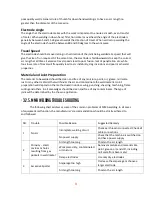
Page 21: ...ode tends to stick to the work penetration is poor and beads with a distinct rounded profile will be deposited Too high current is accompanied by overheating of the electrode resulting undercut and burning through of the base metal and producing excessive spatter Normal current for a particular job may be considered as the maximum which can be used without burning through the work over heating the...

Page 22: ...ture paint oil grease mill scale rust or any other material that will hinder the arc and contaminate the weld material Joint preparation will depend on the method used include sawing punching shearing machining flame cutting and others In all casesedges should be clean and free of any contaminates The type of joint will be determined by the chosen application 3 2 5 MMA Welding trouble shooting The...

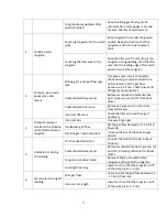
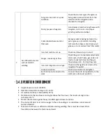
Page 23: ... the correct joint design and fit up 6 Excessive penetration burn through Excessive heat input Reduce the amperage or use a smaller electrode Incorrect travel speed Try increasing the weld travel speed 7 Uneven weld appearance Unsteady hand wavering hand Use two hands where possible to steady up practise your technique 8 Distortion movement of base metal during welding Excessive heat input Reduce ...

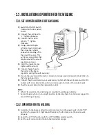
Page 24: ...osed and slowly open the Argon Cylinder Valve to the fully open position 8 Connect the ground clamp to your work piece Contact with the work piece must be firm contact with clean bare metal with no corrosion paint or scale at the contact point 9 Plug the power cable into the appropriate outlet NOTE When TIG operation the shielded gas is inputted to welding gun directly Secure the gas cylinder in a...

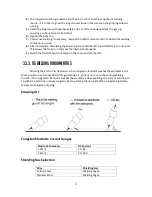
Page 25: ...the fan to run and cool the internal components 9 Switch the ON OFF Switch located on the rear panel to the OFF 3 3 3 TIG Welding Fundamentals Stricking the arc for TIG Operation when tungsten electrode touches the workpiece the short circuit current is only 28A After generating arc current can rise to the setting welding current If the tungesten electrode touches the workpiece when welding the cu...

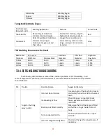
Page 26: ...50 25 35 1 0mm 1 6mm 5LPM 1 6mm 70 90 50 70 1 6mm 1 6mm 7LPM 3 2mm 90 115 90 110 1 6mm 2 4mm 7LPM 3 3 4 DC TIG Welding trouble shooting The following chart addresses some of the common problems of DC TIG welding In all cases of equipment malfunction the manufacturer s recommendations should be strictly adhered to and followed NO Trouble Possible Reason Suggested Remedy 1 Tungsten burning away quic...

Page 27: ...s like paint grease oil and dirt from base metal Contaminated filler wire Remove all grease oil or moisture from filler metal Incorrect filler wire Check the filler wire and change if necessary 4 Yellowish residue smoke on the alumina nozzle discoloured tungsten Incorrect Gas Use pure Argon gas Inadequate gas flow Set the gas flow between 10 15 l min flow rate Alumina gas nozzle too small Increase...

Page 28: ...ck hoses gas valve and torch are not restricted Set the gas flow between 10 15 l min flow rate Incorrect tungsten size or type Check and change the size and or the tungsten if required Loose connection Check all connectors and tighten Earth clamp not connected to work Connect the earth clamp directly to the work piece wherever possible 3 4 Operation environment Height above sea level 1000 M Operat...

Page 29: ...orking area and especially children Do not watch the arc in unprotected eyes Ensure good ventilation of the machine to improve Duty Cycle Turn off the engine when the operation finished for energy consumption efficiency When power switch shuts off protectively because of failure Don t restart it until problem is resolved Otherwise the range of problem will be extended In case of problems contact y...

Page 30: ...atch listen if the arc welding machine has shaking whistle calling or peculiar smell If there is one of the above problems find out the reason and clear it If you can t find out the reason please contact your local service repair station or distributor Agent Observe that the display value of LED is intact If the display number is not intact please replace the damaged LED If it still doesn t work p...

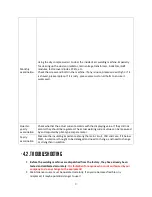
Page 31: ...f they did not accord they should be regulated The actual welding current value can be measured by and adjusted by plier type ampere meter Yearly examination Measure the insulating impedance among the main circuit PCB and case if it below 1MΩ insulation is thought to be damaged and need to change and need to change or strengthen insulation 4 2 Troubleshooting Before the welding machines are dispat...

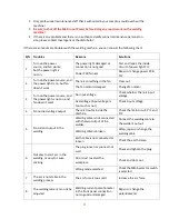
Page 32: ...er source and the power light is not on and fan doesn t work No input voltage Check whether there is input voltage Overvoltage Input voltage is too much or not Check input voltage 4 No no load voltage output There is trouble inside the machine Check the main circuit Pr1 and Pr2 5 No current output in the welding Welding cable is not connected with the two output of the welder Connect the welding c...

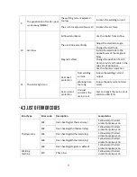
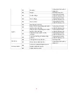
Page 33: ...welding current Induce the welding current output Working time too long Induce the duty cycle interval work Over current protection Unusual current in the main circuit Test and repair the main circuit and drive PCB Pr1 4 3 List of error codes Error Type Error code Description Lamp status Thermal relay E01 Over heating 1st thermal relay Yellow lamp thermal protection always on E02 Over heating 2nd ...

Page 34: ... machine Yellow lamp thermal protection always on E21 Other faults on operating panel when switch on the machine Yellow lamp thermal protection always on E22 Torch fault when switch on the machine Yellow lamp thermal protection always on E23 Torch fault during normal working process Yellow lamp thermal protection always on Accessory E30 Cutting torch disconnection Red lamp blink E31 Water cooler d...

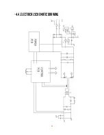
Page 35: ...35 4 4 Electrical schematic drawing ...

Page 36: ...36 200ARC DV STICK TIG ...

Reviews: