background image


2


To resize thickness, move all items on the front cover to left or right

 on the master page.

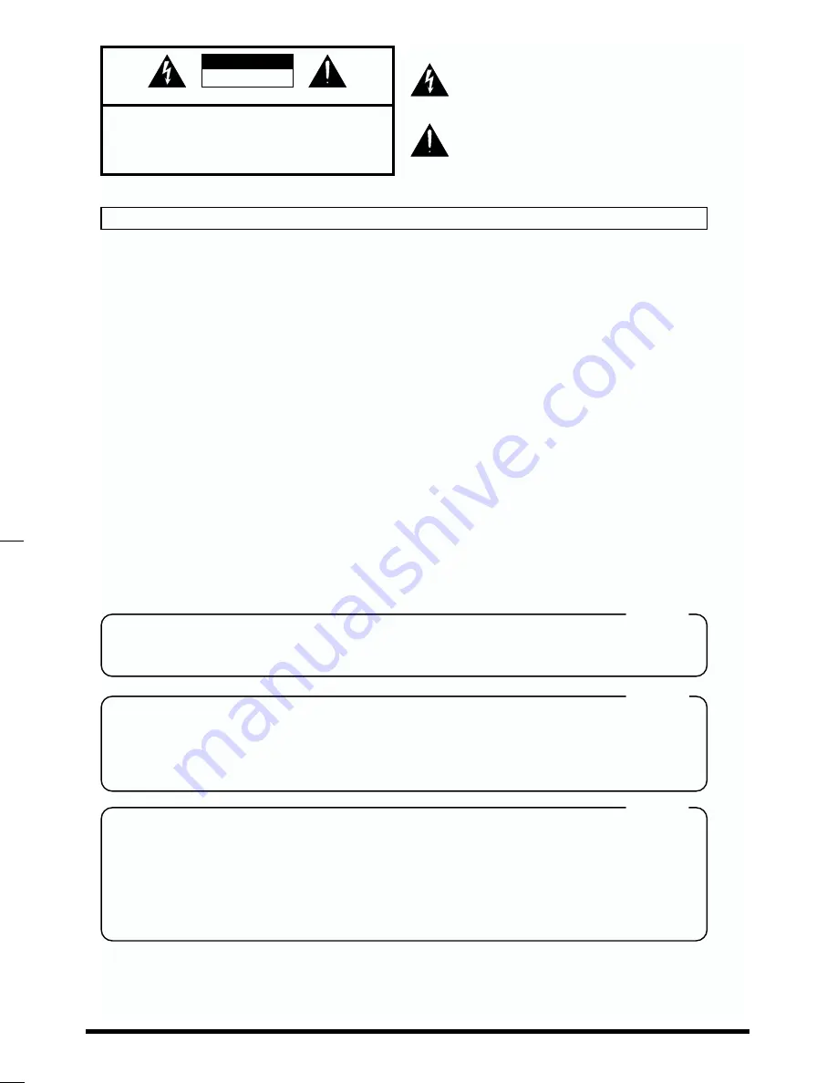
CAUTION

RISK OF ELECTRIC SHOCK

DO NOT OPEN

ATTENTION

: RISQUE DE CHOC ELECTRIQUE NE PAS OUVRIR

CAUTION:   TO REDUCE THE RISK OF ELECTRIC SHOCK,

DO NOT REMOVE COVER (OR BACK).

NO USER-SERVICEABLE PARTS INSIDE.

REFER SERVICING TO QUALIFIED SERVICE PERSONNEL.

The lightning flash with arrowhead symbol, within an 
equilateral triangle, is intended to alert the user to the 
presence of uninsulated “dangerous voltage” within the 
product’s enclosure that may be of sufficient magnitude to 
constitute a risk of electric shock to persons.

The exclamation point within an equilateral triangle is 
intended to alert the user to the presence of important 
operating and maintenance (servicing) instructions in the 
literature accompanying the product.

INSTRUCTIONS PERTAINING TO A RISK OF FIRE, ELECTRIC SHOCK, OR INJURY TO PERSONS.

IMPORTANT SAFETY INSTRUCTIONS

SAVE THESE INSTRUCTIONS

WARNING - When using electric products, basic precautions should always be followed, including the following:

Read all the instructions before using the product.
Do not use this product near water — for example, near a 
bathtub, washbowl, kitchen sink, in a wet basement, or near 
a swimming pool, or the like.
This product should be used only with a cart or stand that is 
recommended by the manufacturer.
This product, either alone or in combination with an amplifier 
and headphones or speakers, may be capable of producing 
sound levels that could cause permanent hearing loss.  Do 
not operate for a long period of time at a high volume level 
or at a level that is uncomfortable.  If you experience any 
hearing loss or ringing in the ears, you should consult an 
audiologist.
The product should be located so that its location or position 
does not interfere with its proper ventilation.
The product should be located away from heat sources such 
as radiators, heat registers, or other products that produce 
heat.
The product should be connected to a power supply only of 
the type described in the operating instructions or as marked 
on the product.

1.
2.

3.

4.

5.

6.

7.

8.

9.

10.

11.

A.
B.

C.
D.

E.

The power-supply cord of the product should be unplugged 
from the outlet when left unused for a long period of time.
Care should be taken so that objects do not fall and liquids 
are not spilled into the enclosure through openings.
The product should be serviced by qualified service 
personnel when:

The power-supply cord or the plug has been damaged; or
Objects have fallen, or liquid has been spilled into the 
product; or
The product has been exposed to rain; or
The product does not appear to operate normally or 
exhibits a marked change in performance; or
The product has been dropped, or the enclosure 
damaged.

Do not attempt to service the product beyond that described 
in the user-maintenance instructions.  All other servicing 
should be referred to qualified service personnel.

IMPORTANT: THE WIRES IN THIS MAINS LEAD ARE COLOURED IN ACCORDANCE WITH THE FOLLOWING CODE.

BLUE: 
BROWN: 

As the colours of the wires in the mains lead of this apparatus may not correspond with the coloured markings identifying 
the terminals in your plug, proceed as follows:
The wire which is coloured BLUE must be connected to the terminal which is marked with the letter N or coloured BLACK.
The wire which is coloured BROWN must be connected to the terminal which is marked with the letter L or coloured RED.
Under no circumstances must either of the above wires be connected to the earth terminal of a three pin plug.

NEUTRAL
LIVE

For the U.K.

This product may be equipped with a polarized line plug (one blade wider than the other) . This is a safety feature. If you 

are unable to insert the plug into the outlet, contact an electrician to replace your obsolete outlet. Do not defeat the safety 
purpose of the plug.

For Polarized Line Plug

CAUTION:
ATTENTION:

TO PREVENT ELECTRIC SHOCK, MATCH WIDE BLADE OF PLUG TO WIDE SLOT, FULLY INSERT.

POUR ÉVITER LES CHOCS ÉLECTRIQUES, INTRODUIRE LA LAME LA PLUS LARGE DE LA FICHE 
DANS LA BORNE CORRESPONDANTE DE LA PRISE ET POUSSER JUSQU' AU FOND.

For the USA

For Canada

For the USA

FEDERAL COMMUNICATIONS COMMISSION

RADIO FREQUENCY INTERFERENCE STATEMENT

This equipment has been tested and found to comply with the limits for a Class B digital device, pursuant to Part 15 of the 
FCC Rules. These limits are designed to provide reasonable protection against harmful interference in a residential 
installation. This equipment generates, uses, and can radiate radio frequency energy and, if not installed and used in 
accordance with the instructions, may cause harmful interference to radio communications. However, there is no guarantee 
that interference will not occur in a particular installation. If this equipment does cause harmful interference to radio or 
television reception, which can be determined by turning the equipment off and on, the user is encouraged to try to correct the 
interference by one or more of the following measures:

–   Reorient or relocate the receiving antenna.
–   Increase the separation between the equipment and receiver.
–   Connect the equipment into an outlet on a circuit different from that to which the receiver is connected.
–   Consult the dealer or an experienced radio/TV technician for help.

Unauthorized changes or modification to this system can void the users authority to operate this equipment.
This equipment requires shielded interface cables in order to meet FCC class B Limit.

This product complies with the requirements of European Directives EMC 89/336/EEC and LVD 73/23/EEC.

For EU Countries

For Canada

This Class B digital apparatus meets all requirements of the Canadian Interference-Causing Equipment Regulations.

Cet appareil numérique de la classe B respecte toutes les exigences du Règlement sur le matériel brouilleur du  Canada.

NOTICE

AVIS

Summary of Contents for U-8ST

Page 1: ...roper operation of the unit Additionally in order to feel assured that you have gained a good grasp of every feature provided by your new unit Getting Started should be read in its entirety The manual...

Page 2: ...ly only of the type described in the operating instructions or as marked on the product 1 2 3 4 5 6 7 8 9 10 11 A B C D E The power supply cord of the product should be unplugged from the outlet when...

Page 3: ...ever climb on top of nor place heavy objects on the unit 107b Never handle the power cord or its plugs with wet hands when plugging into or unplugging from an outlet or this unit 108a Before moving th...

Page 4: ...ount of heat will radiate from the unit during normal operation 558a To avoid disturbing your neighbors try to keep the unit s volume at reasonable levels You may prefer to use headphones so you do no...

Page 5: ...ording the Guitar Vocals and Chorus 55 Step 3 Press the GUITAR INST Button or the MIC Button to Get Ready to Record 55 Using Effects to Create Sounds 58 Finishing Up the Song 59 Step 4 Press the MIX D...

Page 6: ...U 8 with a Computer Installing the U 8 Driver p 22 Before you install the U 8 driver be sure to read Before You Install the U 8 Driver p 20 Cubasis VST U 8 Cubasis VST U 8 is digital recording softwar...

Page 7: ...u can play and record MIDI data without an external sound module using only your computer For how to install VSC 3 0 refer to p 35 Demo Songs These are demo songs for Cubasis VST U 8 Style Data SMF St...

Page 8: ...Please fill out and send in the registration card that comes in this package Doing so will make sure you are entitled to technical suport and kept aware of updates and other news regarding Cubasis VS...

Page 9: ...d on No special settings are required Optical Digital Input Output You can digitally acquire sounds from MDs and CDs for use as backing data or record mastered songs to DAT or MD directly in digital f...

Page 10: ...ices and music files that meet the General MIDI standard bear the General MIDI logo Music files bearing the General MIDI logo can be played back using any General MIDI sound generating unit to produce...

Page 11: ...demarks of Steinberg Soft und Hardware GmbH Adobe Acrobat is a trademark of Adobe Systems Incorporated Microsoft Windows and Windows NT are registered trademarks of Microsoft Corporation 206c Windows...

Page 12: ...imes it s used to answer no to questions 4 CURSOR Buttons Move the cursor and item selections up down left and right 5 Record Indicator Lights up during recording 6 Playback Indicator Lights up to sho...

Page 13: ...cator Set Button TAP Pressing the Locator 1 or 2 button while holding down this button sets the present song position as the corresponding Locate point 27 MIXER Button Displays the Mixer Control scree...

Page 14: ...g it through your multi effects processor or similar equipment It s also for connection to synthesizer output 6 Guitar Input Jack This is for direct high impedance connection to a guitar When using th...

Page 15: ...e knob on the top panel to adjust the volume level for headphones You will need to acquire and have on hand whatever equipment or cables other than what came with the U 8 that you need When doing this...

Page 16: ...t jack If it is a 1 4 phone plug connect it to the A Input jack 983 Howling could be produced depending on the location of microphones relative to speakers This can be remedied by 1 Changing the orien...

Page 17: ...in the above diagram to a device that passes the input sound through to its output an MD DAT CD R that is recording the U 8 and that device will form a loop that can cause oscillation producing an un...

Page 18: ...e Power Supply Connect the power cable to the AC inlet and a power outlet fig 04 10 941 1 AUX IN LINE OUT MIDI sound module U 8 R L R L AUX IN B A MIC INPUT GUITAR Hi Z OUTPUT 2 MIDI sound module FOOT...

Page 19: ...or playing backing performances using a sequencer is not included MIDI performances are also possible with software MIDI synthesizers but in cases of real time MIDI input and the like we recommend con...

Page 20: ...is already installed in your computer you must delete it as explained in Deleting the U 8 Driver p 67 Exit all other Windows applications before you install the U 8 driver If you will be connecting yo...

Page 21: ...the Voice Modem Wave 00 Line and or Voice Modem Wave 00 Handset devices to the Disabled state 1 Click the Windows Start button point to Settings and select Control Panel Next in the Control Panel doub...

Page 22: ...ion procedure cannot be continued so click Cancel to terminate the installation procedure Afterwards while referring to If Installation Doesn t Proceed As It Should Check the Following Points p 24 pro...

Page 23: ...ROM drive and click OK 6 Verify that Roland U 8 USB Driver is displayed as the model and click Next fig 05 04 e eps_50 7 Click Next fig 05 05 e eps_50 Installation of the U 8 Driver will begin In this...

Page 24: ...details on installing an additional hard disk refer to the owner s manuals for your computer and for Windows Was another program running during installation Quit all other programs then repeat the in...

Page 25: ...XT PREV MIC MARKER 4 50dBm AUX B R A L MIC GUITAR Hi Z FOOT SW OUT IN MIDI USB OUT IN DIGITAL POWER 1 8 1 8 AUDIO AUDIO MIDI MIDI MIDI 9 16 EZ RECORDING INPUT SENS PEAK PHONES REC MONITOR 4 50dBm U 8...

Page 26: ...r Playback unchanged and jump to step 4 For Playback at Preferred device click and choose 1 U 8 WAVE OUT 1 MASTER to output warning sounds from Windows audio output from Media Player or the like from...

Page 27: ...Panel Then in Control Panel double click Multimedia The Multimedia Properties dialog box appears 2 Click the MIDI tab 3 At MIDI Output from the Single Instrument list select 1 U 8 MIDI OUT This cause...

Page 28: ...and then click Run The Run dialog will appear 3 In the Open text box input E Setup exe and then click OK Alternatively you can click Browse then open the CD ROM drive select the Setup exe file and cli...

Page 29: ...case select Yes I want to restart my computer now and click OK After restarting your computer perform the entire installation procedure over again from Step 1 Case 2 If the U 8 Driver Not Found dialog...

Page 30: ...whether you want to install Acrobat Reader Acrobat Reader is a program that is necessary for reading document regarding Cubasis VST U 8 If you want to install the program click Yes fig 05 08f e eps_5...

Page 31: ...ur screen 10 You will be asked whether you want to restart your computer To make the settings effective choose Yes I want to restart my computer now in the dialog box then click Finish Windows will re...

Page 32: ...Multimedia Setup window click the Advanced Options button to open the ASIO Multimedia Setup Advanced Options dialog 4 In the Device Name for Output Ports check 1 U 8 WAVE OUT 1 MASTER and 1 U 8 WAVE O...

Page 33: ...From the Windows Start menu select Programs Steinberg Cubasis VST Setup MME to execute it 2 Click and select the device to use for MIDI Input from the MME Inputs If you will be using the MIDI IN Conne...

Page 34: ...ollowing dialog appears fig 0 5 eps_50 Click Yes then the Audio system test starts fig 0 6 eps_50 If the test finished successfully this completes the settings for Cubasis VST U 8 If it does not finis...

Page 35: ...ons VSC 3 0 is a multitimbral sound module featuring 16 parts for a maximum of 128voices In addition VSC 3 0 comes with 902 sounds and 26 drum sets using SC 88Pro Map compatible sound sets built in ma...

Page 36: ...Taskbar lets you make settings for VSC 3 0 easily right from the desktop Installing VSC 3 0 1 Start up Windows If you have already started other software quit them beforehand 2 Insert the included CD...

Page 37: ...if you already have VSC 55 88 installed on your computer If this message does not appear then please go to Step 9 fig 1 5 If you want to easily reinstall the currently installed VSC 3 0 or VSC 55 88...

Page 38: ...ferent folder click Browse and select another folder fig 1 7 10 The Question dialog box will appear If the displayed settings are correct click Next The installation starts fig 1 8 Check this if you w...

Page 39: ...ings to use Cubasis VST U 8 with VSC3 0 Preparation to use VSC 3 0 1 Make sure that the power on the U 8 is turned on then start up Cubasis VST U 8 2 In Cubasis VST U 8 choose System from the Audio me...

Page 40: ...ings Performance to open the VSC 3 0 Settings Window 2 Click 44 1KHz for the Sampling Rate fig 1 12 3 Click the Device tab 4 Click Select Windows audio and MIDI settings from VSC 5 Click DirectSound O...

Page 41: ...click No to proceed fig 1 14 3 Click the Advanced Options button to open the ASIO Multimedia Setup Advanced Options dialog 4 In the Device Name for Output Ports click the check box beside Roland VSC...

Page 42: ...gs for the MIDI device 1 From the Windows Start menu select Programs Steinberg Cubasis VST Setup MME to open the Steinberg Setup MME dialog 2 Select Roland VSC 3 0 for MME Outputs and press the Move u...

Page 43: ...for Roland VSC 3 0 in the ASIO Multimedia Setup Advanced Options dialog box p 41 may also solve the problem Pressing the Detect Buffer Size button will set a suitable value for the buffer size automa...

Page 44: ...3 0 Settings Device 3 Click Select Windows audio and MIDI settings from VSC 4 Click DirectSound Off and choose Selecting Automatically or a device other than 1 U 8 WAVE OUT1 2 fig 1 21 5 Check Select...

Page 45: ...and press the Move up button so that it appears at the top of the list fig 1 23 3 Click OK to close the dialog Settings for the AUDIO device 1 Select Windows Start Programs Steinberg Cubasis VST ASIO...

Page 46: ...2 EFFECTS Confirm that Sync Reference for 1 U 8 WAVE OUT 1 MASTER is set to Yes If not click 1 U 8 WAVE OUT 1 MASTER then press the Move up button so that it appears at the top of the list fig 1 25 5...

Page 47: ...he following dialog appears fig 1 27 Click Yes then the Audio system test starts fig 1 28 If the test finished successfully this completes the settings to play songs via VSC 3 0 If it does not finish...

Page 48: ...e folder by clicking the button to move the folder up one level or by using Look in fig 1 29 3 1 Click the demo song from the list Here you select Special_U ALL 2 Click the Open button fig 1 30 The di...

Page 49: ...own below and lower the Master Volume Fader to the bottom If you are listening through headphones raise the Headphones Volume to an appropriate level If you connect the U 8 s output to a stereo system...

Page 50: ...ear any sound refer to the Points Related to Audio under Troubleshooting in the online manual You may find items that provide a solution to the problem If you are using VSC 3 0 lower the CPU Load refe...

Page 51: ...8 you can also work with wave files files with the extension WAV as audio data One feature of audio data is that like cassette tapes and MDs you can faithfully record any sound However one minute of a...

Page 52: ...A software MIDI synthesizer lets you play MIDI data using just your computer but by using an external MIDI sound module such as the SC 8850 SC 8820 or SC 88Pro you can play sounds of even greater vari...

Page 53: ...m commercially available MIDI data collections Backing parts are made from audio data Wave files Import sound from a CD MD or the like to the sequencer program and use it as backing for what you play...

Page 54: ...uencer and begin playback of the CD MD or the like the sounds input from these gear are recorded to the sequencer For more information refer to the corresponding sections in the online manuals Connect...

Page 55: ...g preparations for recording of the guitar are made when the U 8 Controller is used 1 Click and select a recording track in the Arrange Window of Cubasis VST U 8 If you want to record in STEREO set th...

Page 56: ...ffect Setting dialog box 1 press the U 8 s SELECT button to select whether to apply effects then 2 press the CURSOR buttons or turn the TIME VALUE dial to move the cursor and press the ENTER button to...

Page 57: ...Other Instrument Finish Getting Ready for Recording dialog box press the NEXT button or click Finish to close the dialog box fig 10 30e e eps_50 While the above describes the process of setting up fo...

Page 58: ...2 Press the CURSOR buttons or turn the TIME VALUE dial to choose the Wet Vocal patch from Vocal then press the ENTER button to change the sound to the patch After making the selection press the EXIT...

Page 59: ...U 8 Mixer is used 1 Pressing the MIX DOWN button on the U 8 displays the EZ RECORDING Mixdown Effect Setting dialog box 2 At the EZ RECORDING Mixdown Effect Setting dialog box use the CURSOR buttons t...

Page 60: ...are used when recording guitars and mic sources are applied to a single input whereas the System effects are used for adding effects to the overall mix As shown in the figure below when System effect...

Page 61: ...the knob using the mouse while holding the ALT key 8 After settling the final mix level select the record track and press the Record Button to record the song You can audition the effect applied soun...

Page 62: ...ing starts press the Play button to start playback of the song or use the sequencer to play back the data 4 When the song ends stop recording on the recording device then press the Stop button to stop...

Page 63: ...included CD ROM into your CD ROM drive 2 Click the Windows Start button and click Run The Run dialog will appear 3 In the Open text box input E Acrobat Reader ar405eng exe and then click OK Alternati...

Page 64: ...lick Troubleshooting The browser window appears fig 10 20 e eps_50 2 The web browser screen opens After the screen title and table of contents is displayed you can then click to jump to a desired item...

Page 65: ...tal mixer and more U 8 Controller Manual This describes how to use U 8 Controller U 8 Tuner Manual This describes how to use U 8 Tuner 1 After clicking the Windows Start button go to Programs and sele...

Page 66: ...e Auxiliary and Digital Inputs and Setting the Levels When Connected to the Digital Input In the Mixer window of the U 8 Controller select DIGITAL for the INPUT setting in INPUT AUX When Connected to...

Page 67: ...a Computer Installing the U 8 Driver p 22 to install the driver Settings for the U 8 Driver Depending on your computing setup problems may occur in audio and MIDI playback The U 8 driver provides seve...

Page 68: ...ndows Explorer and from Windows Explorer s View menu choose Folder Options 9 Click the View tab and under Files and Folders Advanced settings in Hidden Files click Show all files then click OK fig 12...

Page 69: ...n Device below Other Devices and Universal Serial Bus Controllers then install the driver once again 1 Disconnect all USB devices connected to the computer except the U 8 USB mouse and USB keyboard Th...

Page 70: ...lick Close to close the dialog box Removing Uninstalling a Program The programs on the included CD ROM are compatible with the Add Remove Programs feature in Windows If you no longer need a particular...

Page 71: ...select Roland U 8 USB Digital Studio In this case you cannot uninstall one of the two programs If you installed both of the programs they are all uninstalled at the same time To uninstall VSC 3 0 sel...

Page 72: ...72 Information That You Will Find Useful Effect Algorithm List Space Multi fig 66 01 Guitar Multi fig 66 02 Vocal Multi fig 66 04 2ch RSS fig 66 05 Mastering fig 66 10...

Page 73: ...d compressor BCH Threshold BCHL Threshold BCHR Threshold BCL Threshold BCLL Threshold BCLR Threshold Adjust the level at which the effect will begin to apply BCH Both channel L R of the high compresso...

Page 74: ...ow level signals are boosted Larger values will result in longer sustain CS Attack Adjust the time from when the input level exceeds the threshold level to when the effect begins to apply CS Level Adj...

Page 75: ...the high frequency range BF Low Cut Adjusts the frequency below which the flex band filter cut the low frequency range BF Level Adjusts the volume ST Sw switch Turns the lo fi saturator effect on off...

Page 76: ...justs the volume RSS Output Mode Specify the method that will be used to hear the sound The optimal 3D effect will be achieved if you select Speaker when using speakers or Phones when using headphones...

Page 77: ...eter adjusts the amount of feedback Changing the amount of feedback causes the number of time the delayed sound is repeated to change as well DL HF Damp L DL HF Damp R Adjust the degree of HF damping...

Page 78: ...List folder and view index htm At the list you can listen to sample sounds for some patches The Style Data SMF Style data comprise typical performance patterns representing a variety of musical genres...

Page 79: ...B or more Required Free Hard disk Space 100 MB or more Hardware requirements CD ROM Drive Required Software Netscape Navigator version 4 0 or later Microsoft Internet Explorer version 4 0 or later 986...

Page 80: ...or a sound card supporting Windows 98 Windows 95 16 bit stereo 44 1 22 05 11 025 kHz sampling rate CD ROM drive Microsoft Internet Explorer version 3 01 or later or Netscape Navigator version 3 01 or...

Page 81: ...greater Headphones jack 20 to 50 ohms Residual Noise Level input terminated with 1 k ohms A B Input Sensitivity Volume Knob min Line Input jack 4 dBm IHF A typ Line Output jacks 96 0 dBm or less Conne...

Page 82: ...l Sherooq Bldg No 14 Grand Floor DUBAI U A E P O Box 8050 DUBAI U A E TEL 04 360715 EGYPT Al Fanny Trading Office P O Box 2904 El Horrieh Heliopolos Cairo EGYPT TEL 02 4185531 REUNION Maison FO YAM Ma...

Page 83: ...83 MEMO...

Page 84: ...84 MEMO...

Page 85: ...Connector 14 Removing Uninstalling a Program 70 S Side Panel 14 A Input Jack 14 AUX Input Jacks 14 B Input Jack 14 Guitar Input Jack 14 Headphones Jack 14 Line Output Jacks 14 Mic Input Jack 14 Speak...

Page 86: ...p Button 12 TIME VALUE Dial 12 To Start of Song Button 12 Track Group Indicators 13 Track Group Select Button 13 Track Status Buttons 13 Track Volume Faders 13 WINDOW Button 13 U U 8 Controller 7 U 8...

Page 87: ...t off and on the user is encouraged to try to correct the interference by one or more of the following measures Reorient or relocate the receiving antenna Increase the separation between the equipment...

Page 88: ...02234656 00 03 A3 11N...

Reviews: