1
MANUALE DI ISTRUZIONE
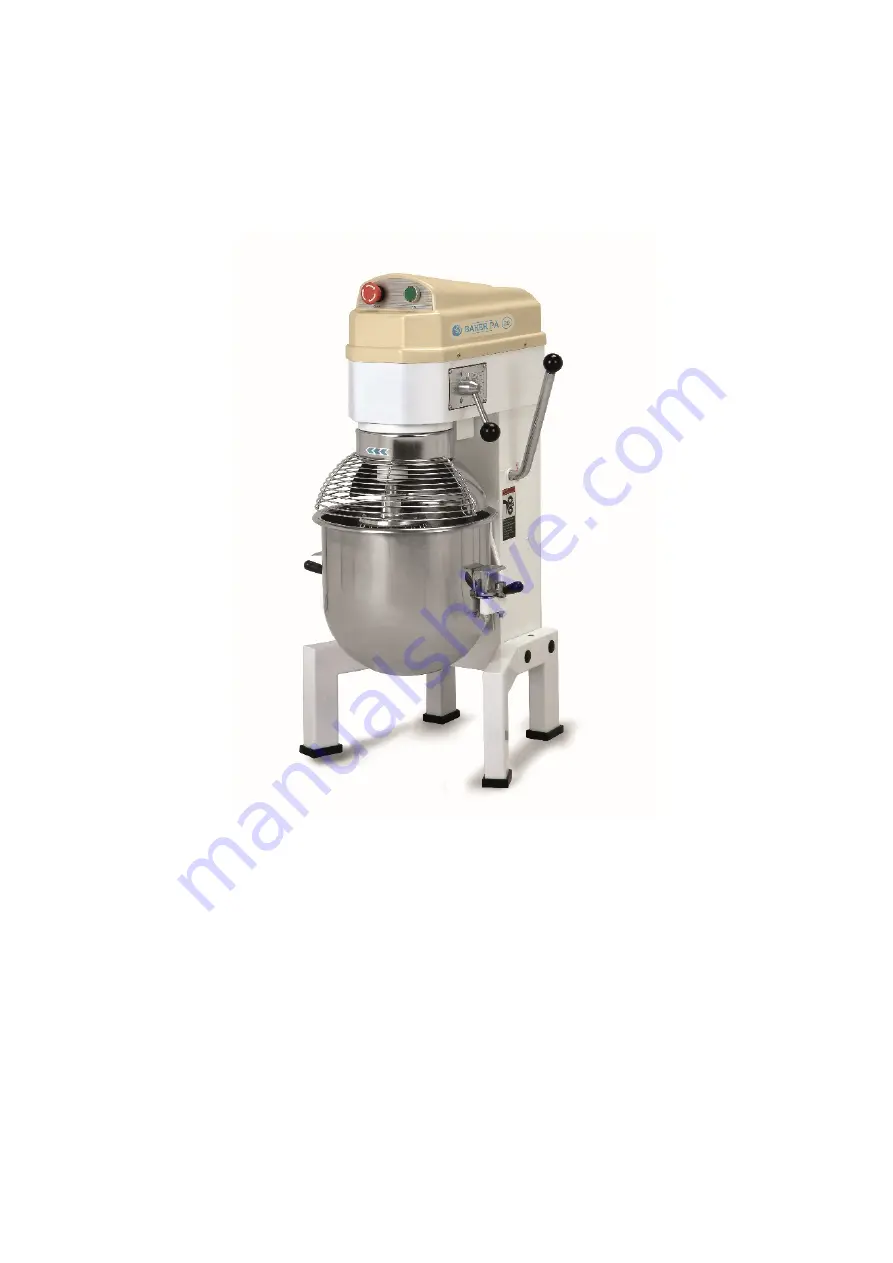
PLANETARIA PA10 - PA20
Manuale d’installazione uso e manutenzione impastatrice planetaria
Installation, operating and service instructions revolving mixer
Page 1: ...1 MANUALE DI ISTRUZIONE PLANETARIA PA10 PA20 Manuale d installazione uso e manutenzione impastatrice planetaria Installation operating and service instructions revolving mixer...
Page 2: ...16 SPECIFICHE TECNICHE PAG 17 SCHEMA ELETTRICO PAG 18 FIGURA 1 STRUTTURA DEL MACCHINARIO 1 PAG 19 FIGURA 2 STRUTTURA DEL MACCHINARIO 2 PAG 20 FIGURA 3 ASSE CENTRALE PAG 21 FIGURA 4 ASSE INGRANAGGIO P...
Page 3: ...nto contenuto in questo manuale Rispettare in particolare le seguenti indicazioni 1 installare la macchina in conformit alle istruzioni riportate al paragrafo 2 non rimuovere le protezioni e non modif...
Page 4: ...UNZIONALIT Aprire l imballo e verificare l integrit di tutti i componenti Effettuare il sollevamento della macchina e posizionarla nella zona adibita all installazione Posizionare la macchina su di un...
Page 5: ...n senso opposto il volantino leva laterale MONTAGGIO UTENSILE 1 Abbassare completamente la vasca ruotando il volantino leva laterale 2 Aprire la griglia ed inserire l utensile sull albero ruotandolo i...
Page 6: ...E RICICLAGGIO La presenza del bidoncino barrato sulla targhetta dati dell apparecchiatura indica che essa al termine della propria vita utile dovr seguire per il suo smaltimento e riciclaggio quanto p...
Page 7: ...dalla portata dei bambini 8 Il macchinario deve essere fissato su un pavimento asciutto e in una zona sicura 9 Se il cavo elettrico rotto procedere alla sostituzione affidandosi a dei professionisti...
Page 8: ...l pezzo Difficolt nel muovere su e gi la ciotola Guida di scorrimento arrugginita Pulire la guida di scorrimento e lubrificare Il motore surriscaldato e la velocit rimane bassa Voltaggio insufficiente...
Page 9: ...AG 15 TROUBLESHOOTING PAG 16 SPECIFICTION PAG 17 ELECTRIC DIAGRAM PAG 18 FIGURE 1 FULL MACHINE PAG 19 FIGURE 2 FULL MACHINE PAG 20 FIGURE 3 CENTRALE AXLE PAG 21 FIGURE 4 GEAR AXLE PAG 22 FIGURE 5 INIT...
Page 10: ...careful reading of the contents of this manual In particular the following instructions must be respected 1 install the machine according to the instructions explained in paragraph 2 do not remove pro...
Page 11: ...INSTALLATION AND FUNCTIONING TESTS Open the carton and make sure that all components are intact Lift the machine according to the instructions and place it in its selected setting for installation Pla...
Page 12: ...side PLACEMENT TOOL 1 Lower the bowl completely by rotating the handwheel lever side 2 Open the lid and insert the tool on the shaft Then lock it by rotating it counter clockwise 3 Close the lid and...
Page 13: ...t the end of its working life the utensil must be disposed of and recycled according to European Directive The Directive provides for the separate collection of electric and electronic equipment by a...
Page 14: ...ge it by professionals SPECIAL ATTENTION 1 Before using please clean the bowl and the mixing devices carefully and then install the bowl onto the machine correctly and tightly 2 When choosing mixing d...
Page 15: ...ak oil Sealing washer is damaged Change Difficult to move the bowl up and down Slideway is rusted Clean the slideway and lubrication The motore is overheat and speed down The voltage is not enought or...
Page 16: ...460 frusta Whisk 540 frusta Whisk 234 spatola Beater 276 spatola Beater 118 uncino Hook 140 uncino Hook Numero di giri al minuto V 110 120 R P M Mixing Speed 648 frusta Whisk 331 spatola Beater 168 u...
Page 17: ...K3 interruttore _ switch K4 interruttore sollevamento ciottola bowl lifting switch K5 Interruttore griglia di protezione safety net switch K0 Interruttore di accensione start switch CA condensatore _...
Page 18: ...k 7 Pannello Name plate 8 Leva Handle 9 Pannello posteriore Rear window 10 Supporto Stand 11 Flangia Flange Knot 12 Vite Screw 13 Manico della ciotola Bowl handle 14 Braccio Arm 15 Pannello posteriore...
Page 19: ...ovella Crank 35 Cavo Wire 36 Asta di tiro Pull pole 37 Vite Screw 38 Asse di regolazione Regulation shaft 39 Dado Nut 40 Perno guida Guide Pin 41 Dispositivo AC AC device 42 Perno guida Guide pin knot...
Page 20: ...naggio Gear ring 1 10 Anello separatore Dividing ring 1 11 Ingranaggio di giunzione Joint gear 1 12 Anello cuscinetto Bearing ring 2 13 Chiavetta 6 14 Key 6 14 1 14 Asse centrale Centre axle 1 15 Chia...
Page 21: ...gio Gear axle 1 3 Chiavetta 5 10 Key 5 10 1 4 Chiavetta 5 14 Key 5 14 1 5 Ingranaggio alta velocit High speed gear 1 6 Anello d arresto Stop ring 1 7 Ingranaggio bassa velocit Low speed gear 1 8 Disco...
Page 22: ...ription Qty 1 Vite Screw 1 2 Anello a molla Spring ring 1 3 Disco Plate 1 4 Ruota grande cinghia Big ball wheel 1 5 Nodo Knot 1 6 Cuscinetto 6004 Bearing 6004 1 7 Chiavetta 6 22 Key 6 22 1 8 Asse cing...
Page 23: ...on Qty 1 Asse Axle 1 A2 Dado Nut 1 A3 Molla Spring 1 A4 Asse Shaft 1 A5 Forcella Fork 1 B6 Copiglia Pin 1 B7 Dado eccentrico Eccentricity knot 1 B8 Grano Steel ball 3 B9 Molla di velocit Speed spring...
Page 24: ...TORE _ MOTOR UNIT Numero Item Descrizione Description Qty 1 Vite Screw 1 2 Molla a rondella Spring washer 1 3 Guarnizione Gasket 1 4 Cuscinetti motore Small belt wheel of motor 1 5 Chiavetta Key 1 6 M...
Page 25: ...Turning plate 1 3 Anello Ring 1 4 Dado Nut 1 5 Griglia di protezione Safety net 1 6 Ingranaggio interno Inner gear 1 7 Vite Screw 1 8 Ingranaggio Plantaty gear 1 9 Cuscinetto 6203 Bearing 6203 1 10 Cu...
Page 26: ...o alzare il gancio per sbloccarlo ruotarlo in senso orario e tirare verso il basso Tutti gli utensili si adattano perfettamente alla ciotola hanno angoli stondati e sono facilmente rimovibili per la p...