Chapter 8. Appendix
194
●
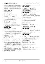
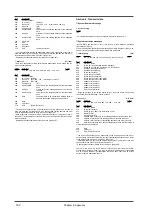
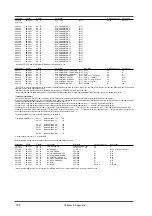
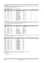
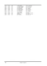
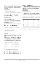
System Parameters [88]
Parameters affecting the entire unit, such as how the two MIDI IN connectors will function, are called System Parameters.
<MODEL ID = 42H>
Address(H)
Size(H)
Data(H)
Parameter
Description Default(H)
Description
00 00 7F
00 00 01
00 - 01
SYSTEM MODE SET
[88]
00
MODE1
00: MODE-1 (Single module mode)
01: MODE-2 (Double module mode)
(Rx. only)
* Refer to "System exclusive messages related to Mode settings" (page 191).
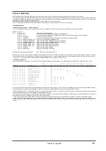
CHANNEL MSG RX PORT
[88]
00 01 00
00 00 01
00 - 01
BLOCK00
PORT A - B
00
PORT A
:
:
:
:
:
00 01 0F
00 00 01
00 - 01
BLOCK0F
PORT A - B
00
PORT A
00 01 10
00 00 01
00 - 01
BLOCK10
PORT A - B
01
PORT B
:
:
:
:
:
00 01 1F
00 00 01
00 - 01
BLOCK1F
PORT A - B
01
PORT B
* You can modify the receiving MIDI port at which channel messages will be received for each BLOCK. We suggest that normally you use PORT A for BLOCK01-0F, and
PORT B for BLOCK10-1F. (In this case there is no need to change the setting.)
* Refer to page 196 for details of each BLOCK.
●
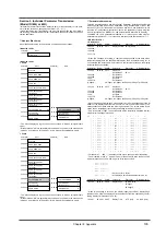
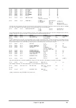
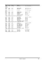
Patch parameters
❍
Patch common parameters
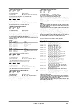
In MODE-1 (Single module mode) this unit functions as a single sound source module with 32 Parts. In MODE-2 (Double module mode) it functions as two sound source mod-
ules with 16 Parts each. The parameters common to all Parts in each module are called Patch Common parameters.
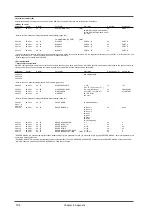
Address(H)
Size(H)
Data(H)
Parameter
Description
Default Value (H)
Descrip-tion
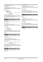
40 00 00
00 00 04
0018 - 07E8
MASTER TUNE
-100.0 - +100.0 [cent]
00 04 00 00
0 [cent]
40 00 01#
Use nibblized data.
40 00 02#
40 00 03#
* Refer to section 5. Supplementary material, "About tuning" (page 208).
40 00 04
00 00 01
00 - 7F
MASTER VOLUME
0 - 127
7F
127
(= F0 7F 7F 04 01 00 vv F7 )
40 00 05
00 00 01
28 - 58
MASTER KEY-SHIFT
-24 - +24 [semitones]
40
0[semitones]
40 00 06
00 00 01
01 - 7F
MASTER PAN
-63 (LEFT) - +63 (RIGHT)
40
0 (CENTER)
40 00 7F
00 00 01
00
MODE SET
00 = GS Reset
(Rx. only)
* Refer to "System exclusive messages related to Mode settings" (page 191).
40 01 00
00 00 10
20 - 7F
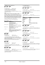
PATCH NAME
16 ASCII Characters
40 01 : #
40 01 0F#
40 01 30
00 00 01
00 - 07
REVERB MACRO
00: Room 1
04
Hall 2
01: Room 2
02: Room 3
03: Hall 1
04: Hall 2
05: Plate
06: Delay
07: Panning Delay
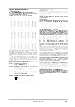
40 01 31
00 00 01
00 - 07
REVERB CHARACTER
0 - 7
04
4
40 01 32
00 00 01
00 - 07
REVERB PRE-LPF
0 - 7
00
0
40 01 33
00 00 01
00 - 7F
REVERB LEVEL
0 - 127
40
64
40 01 34
00 00 01
00 - 7F
REVERB TIME
0 - 127
40
64
40 01 35
00 00 01
00 - 7F
REVERB DELAY FEEDBACK
0 - 127
00
0
40 01 37
00 00 01
00 - 7F
REVERB PREDELAY TIME
[88]
0 - 127[ms]
00
0
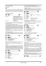
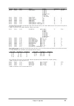
* REVERB MACRO is a macro parameter that allows global setting of reverb parameters. When you select the reverb type with REVERB MACRO, each reverb parameter will
be set to the most suitable value.
* REVERB CHARACTER is a parameter that changes the reverb algorithm. The value of REVERB CHARACTER corresponds to the REVERB MACRO of the same number.
* In MODE-2 (Double module mode), REVERB PREDELAY TIME cannot be used.
Summary of Contents for SoundCanvas SC-88 Pro
Page 9: ...Chapter 1 Try out the unit Quick start Chapter 1...
Page 18: ...Chapter 1 Try out the unit 16...
Page 19: ...Chapter 2 Parts and parameters Chapter 2...
Page 47: ...Chapter 3 System Effects Chapter 3...
Page 57: ...Chapter 4 Insertion Effects Chapter 4...
Page 97: ...Chapter 5 Convenient functions Chapter 5...
Page 121: ...Chapter 6 Using the unit with a personal computer Chapter 6...

