11
Panel Descriptions
■
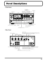
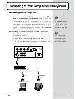
Front Panel
fig.0-3e
■
Rear Panel
fig.0-4e
F2 button
PHONES jack
F1 button
F3 button
F4 button
INSTRUMENT MAP button
SHIFT button
SOLO button
MUTE button
DECREMENT button
INCREMENT button
POWER switch
VOLUME dial
display
EDIT button
DRUM button
EFFECTS button
PART button
VARIATION button
EXIT button
PART button
INSTRUMENT button
ENTER button
VALUE dial
Instrument display area
SERIAL connector/USB connctor
AUDIO INPUT VOLUME knob
INPUT jack
OUTPUT 1 jack
OUTPUT 2 jack
AC IN connector
MIDI IN 1 connector
MIDI IN 2 connector
MIDI OUT 1 connector
MIDI OUT 2 connector
computer switch
USB connector
Set this switch depending on the type of computer connected to the Computer connector,
or the software you are using. Turn the power off before changing the setting of this switch.
If you wish to use the MIDI connectors, set this switch to MIDI.
At the factory settings, no sound is output from the Output 2 jacks
A dedicated Computer cable or USB cable (sold separately) can be connected here.
The type of cable required will depend on your computer.
When the Computer switch is set to MIDI,
the Computer connector or the USB cable cannot be used.


