background image

Chapter 1 Basic Operation

Basic Operation of the iModela Controller

9

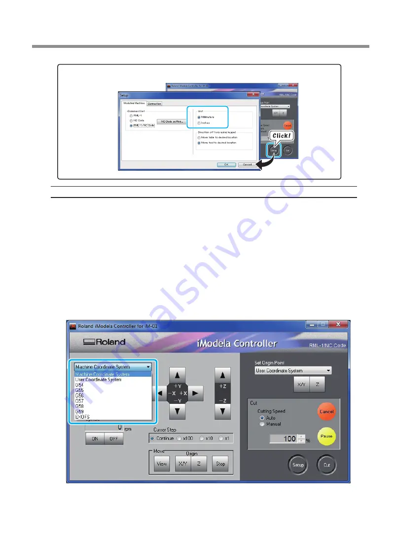
Selecting the Coordinate System That Is Used to Display the Cutting Tool Location

You can select the coordinate system that is used to display the cutting tool location from the following op-
tions.

 User Coordinate System: This coordinate system enables you to freely change the location of the origin.

 Machine Coordinate System: This is a machine-specific coordinate system in which the location of the 

origin is fixed.

 G54 to G59: These are workpiece coordinate systems that are used with NC codes. For details, see the "NC 

Code Reference Manual."

 EXOFS: This is a coordinate system that is used with NC codes. For details, see the "NC Code Reference 

Manual."

If the command set is RML-1, always select "User Coordinate System." EXOFS and the options from G54 to G59 
can only be selected when the command set is "NC Code" or "RML-1/NC Code."

 P. 10, "Selecting the Command Set"

Selecting the Display Unit

Summary of Contents for iModela iM-01

Page 1: ... 01 First Step Guide This guide describes the procedure from checking the accessories to initial cutting Be sure to read this manual before you use the machine for the first time iModela iM 01 Master Guide this guide This guide contains detailed explanations of the machine s features maintenance methods and troubleshoot ing information The manual is in electronic format and no printed document is ...

Page 2: ...n Be Mounted 14 Installing the Cutting Tool and Loading the Cutting Material 15 Starting Cutting 18 Setting the Cutting Origin 18 Starting Cutting for output from iModela Creator 21 Starting Cutting NC code Data 23 Advanced Operations 27 Adjusting Overriding the Feed Rate during Cutting 27 Saving and Reusing Output File Lists 28 Corrections 29 NC Code Setting 30 Testing Output of NC Code Files 31 ...

Page 3: ...ED Beside the Power Button Is Flashing 50 The Deletion of Cutting Data Takes Time 51 To Install iModela Driver Separately 51 To Install Software and Electronic Manual Separately 55 The iModela Driver Cannot Be Installed 56 Uninstalling the iModela driver 57 Responding to Error Messages 59 Responding to Error Messages 59 NC Code Specifications 63 List of Settings Related to NC Code 63 Items Related...

Page 4: ...ew it iModela Creator Start iModela Creator and then click Help Contents Virtual Modela SFEdit2 On the taskbar click Start All Programs choose the software you re using then click Help Start the software and then click Help Contents Viewing the NC Code Reference MANUAL On the taskbar click Start All Programs iModela Manuals then NC Code Reference Manual ...

Page 5: ... Shutting Down the Machine 6 Starting the Machine 6 Shutting Down the Machine 6 Basic Operation of the iModela Controller 7 Operation of the Spindle Unit 7 About the Cutting Tool Location Display 8 Selecting the Command Set 10 About the Command Sets 10 Selecting the Command Set 10 4 ...

Page 6: ...t or right side of the machine In this manual the mechanisms around the spindle unit including the spindle motor are called the spindle head The rotary axis area inside the spindle unit is called the spindle Front cover Main unit Table Rear cover USB port Power cord connector Spindle head Side cover Side cover LEDs Spindle motor Collet Power button ...

Page 7: ...om flashing to on the initialization has finished Start the iModela Controller which is used to control the machine On the taskbar click Start All Programs iModela Controller then iModela Controller Shutting Down the Machine Procedure Click on the iModela Controller The iModela Controller closes Press the power button When the green LED turns off the machine has shut down ...

Page 8: ...ead or table to a specific location Continue The spindle head or table moves continuously while you hold down a feed but ton x100 x10 x1 Each click of a feed button moves the spindle head the specified distance x1 0 01 mm x10 0 1 mm x100 1 mm For display in inches the value in mm is converted into inches View The components move to the view position the spindle head moves to the high est position ...

Page 9: ...0 millimeters along the Z axis The X axis distance is called the X coordinate TheY and Z axis distances are similarly called the Y coordinate and the Z coordinate The distances from the origin to the cutting tool along each axis are the coordinate values About Y Axis Movement Under the factory default settings Y axis movement assumes a direction of cutting tool movement relative to the object bein...

Page 10: ...chine Coordinate System This is a machine specific coordinate system in which the location of the origin is fixed G54 to G59 These are workpiece coordinate systems that are used with NC codes For details see the NC Code Reference Manual EXOFS This is a coordinate system that is used with NC codes For details see the NC Code Reference Manual If the command set is RML 1 always select User Coordinate...

Page 11: ...on to enable the machine to receive cutting programs that use the RML 1 or NC code com mand sets Selecting the Command Set Use the iModela Controller s Confirm dialog box to select the command set Select the appropriate command mode to match the application software to be used If a command that is sent to the machine is different from the command set selected on the iModela Controller an error occ...

Page 12: ... Material 15 Starting Cutting 18 Setting the Cutting Origin 18 Starting Cutting for output from iModela Creator 21 Starting Cutting NC code Data 23 Advanced Operations 27 Adjusting Overriding the Feed Rate during Cutting 27 Saving and Reusing Output File Lists 28 Corrections 29 NC Code Setting 30 Testing Output of NC Code Files 31 Displaying and Saving This Machine s Settings 32 Initializing This ...

Page 13: ...cing the spindle unit or the spindle motor Check When using the machine in a low temper ature environment Check After replacing parts other than the spindle unit or spindle motor Check Check After application of Grease P 38 Application of Grease to X Y Z Axes Check Check Procedure Click in the upper left of the iModela Controller Click Maintenance Click the Confirm tab Note Before checking the ope...

Page 14: ...lication software that you will use For details on the different command sets see page 10 Selecting the Command Set Selecting the Cutting Tool and Cutting Material Selecting the Cutting Tool You can use not only the cutting tool that is included as an accessory but various other cutting tools to meet other needs It s a good idea to use the cutting tools selectively according to the work process su...

Page 15: ...utting material that fills this entire area Clearance to allow the cutting tool to perform no load feeding is necessary in the X Y and Z directions You have to use a cutting material that is small enough to provide this clearance Also the possible cutting in depth is generally determined by the length of the cutting tool If you use a long cutting tool to enable deep cuts there is little clearance ...

Page 16: ...e cutting tool 1 Install the cutting tool Click View on the iModela Controller The spindle head moves to the cen ter andthetablemovestothefront This is the view position Open the front rear and side covers Slowly push the main unit down onto its back Fully insert the cutter into the collet Collet Cutting tool accessory Hook Pull the hooks towowrds you with the part of the handle ...

Page 17: ...ch the blower fan to the cutter Be careful of the blade and fully insert the blower fan 2 Affix the cutting material Affix the double sided tape Ifthetrialcuttingmaterial provided as an accessory is used peel the protective film off of both sides Depending on the cutting method use a scrap plate P 17 Cutting Requiring a Scrap Plate Hexagonal wrench Mounting screw Blower fan Scrap plate Double side...

Page 18: ...riginal state Raise the main unit back into place fix it in place with the hooks and then close the front rear and side covers Cutting Requiring a Scrap Plate There is a need to place a scrap plate when the cutting data contains the process to make a hole in the cutting material The thickness of the scrap plate is decided according to depth of the hole If the scrap plate does not have the sufficie...

Page 19: ...t to perform cutting with this machine you need to set the X Y and Z origins set the XY origin to set the X and Y origins at the same time The X and Y origins are determined by the cutting data and the location of the cutting material When you use iModela Creator if the size of the cutting material set in the cutting data and that of the actual cutting material are the same you can cut almost the ...

Page 20: ...P 7 Operation of the Spindle Unit Click the Z cursor button to lower the tip of the cutting tool to about 1 mm from the material surface Loosen the mounting screw and then adjust the cutter so that its tip contacts the surface of the cutting material When the tip contacts the surface fix the cutter in place again with the mounting screw ...

Page 21: ... has been set to RML 1 Set Origin Point can only be set to User Coordinate System If the cutting data is written using NC code Use Set Origin Point to select the work piece coordinate system that matches the cutting data Click Z under Set Origin Point Set the Z origin to display Z 0 00 mm Raise the cutting tool Next you will move the cutting tool in the X and Y directions Raise the cutting tool to...

Page 22: ... the X andY origins to display X 0 00 mm and Y 0 00 mm Starting Cutting for output from iModela Creator Procedure Start iModela Creator On the taskbar click Start All Programs iModela Creator then iModela Creator Creating the output file For information on how to use iModela Creator such as a drawing method refer to Help of iModela Creator P 3 Viewing the Documentation for the Softwares Setting th...

Page 23: ... Cutting 22 Click Output Cut dialog appears Set the cutting conditions including Cutter and Material For information on how to use iModela Creator refer to Help of iModela Creator P 3 Viewing the Documentation for the Softwares ...

Page 24: ...NC code Data Operation Overview Step 1 Save the output file First convert the program to a text file and save it on your PC This file is known as the output file Step 2 Register the output file and then output it Register the saved output file in the iModela Controller s output file list and then output the file You can also register multiple output files and then output them all consecutively ...

Page 25: ... cause the ma chine to malfunction Is the output file correct Are the origin settings correct Do the cutting parameters match the type of cutting material Procedure Click Cut on the iModela Controller The Cut dialog is displayed Click The Open dialog box is displayed Select the output file and click The selected cutting data file is displayed in the Cut dialog s list of output files If you want to...

Page 26: ...o delete an output file from the output file list select the output file that you want to delete and then click Delete If you click Delete All all the files in the list will be deleted Dragging Cutting Data to the Output File List You can also add cutting data to the list by dragging output files to the windows that are displayed in step Select this check box to pause cutting after a single file i...

Page 27: ...movethecuttingtoolandthecutting material from the machine When the operation resumes initialization is performed on the cutting machine Dependingonthelocationthatthecuttingtoolandcuttingmaterialwereinwhencuttingstopped thecutting tool and cutting material may collide while the machine is restarting This may damage the machine Click this button during cutting to stop cutting Click this button durin...

Page 28: ...th The cutting opera tion is paused if the load being applied exceeds the capabilities of the spindle motor Manual The feed rate during cutting can be manually adjusted A fixed feed rate will be maintained if no operation is performed A higher product quality can be achieved if cutting can be performed with no accelerations or decelerations However the cutting operation is paused if the load being...

Page 29: ...utput file lists By reusing a file list you can eliminate the work required to select the files to construct the same cutting order that you want to repeat Saving Output File Lists Reusing Output File Lists Specify a file name and then click Save Select the list file that you want to use and click Open ...

Page 30: ...ing affects the cutting accuracy Exercise care when you specify this setting If you are not confident in the value that you want to specify we recommend that you do not specify this setting You can make distance corrections for the X Y and Z axes Setting range 99 5 to 100 5 ...

Page 31: ...values in NC codes For the conventional method values are interpreted as millimeters or inches when they contain a decimal point or as thousandths of a millimeter or ten thousandths of an inch when no decimal point is present With the calculator method values are always interpreted as millimeters or inches regardless of whether a decimal point is present When calculator method interpretation is us...

Page 32: ...e program Click this button to execute test output at the maximum cutting tool feed rate All opera tions other than the cutting tool feed rate are executed according to the program You can adjust the feed rate of the cutting tool You can only specify this setting when Manual is selected in the iModela Controller s main window See page 27 Adjusting Overriding the Feed Rate during Cutting Setting un...

Page 33: ...d also to save the settings as a text file This feature is useful when you want to share settings between users when you need to provide setup information when you request repairs for a malfunctioning machine or under similar circumstances Initializing This Machine s Settings Saves the displayed information as a text file Read the confirmation message and then click OK or Cancel ...

Page 34: ...rs the working time of the old mo tor that was in use before you switched motors increases This makes it impossible to manage the motor working time P 43 Replacing the Spindle Motor Usage Example Avoiding stoppages during cutting You can check whether the spindle motor that is currently in use has a long enough work life remaining to complete the cutting operation that you have planned This enable...

Page 35: ...Z Axis Screws 36 Application of Grease to X Y Z Axes 38 Maintenance of the Cutting Tool 40 Replacement of Consumable Parts 41 Caution and Note for Replacement of Consumable Parts 41 Replacement Periods for Consumable Parts 41 Replacing the Spindle Motor 43 Replacing the Hooks 45 34 ...

Page 36: ... be used to collect cutting waste If you cannot confirm that it is safe to use the dust collector use a brush or similar tool to collect cutting waste Do not use the dust collector CAUTION Be careful of high temperatures During use the cutting tool and spindle motor become hot Exercise caution to avoid fire and burns The mechanisms around the spindle unit remain hot for approximately 10 minutes af...

Page 37: ...ion is finished use the cleaning brush provided as an accessory to clean X Y and Z axis screws X Axis Move the spindle unit to the left or right and then thoroughly clean the screw P 7 Operation of the Spindle Unit Y Axis Move the table to the front or back and then thoroughly clean the screw P 7 Operation of the Spindle Unit Screw Screw ...

Page 38: ...ng operation the machine s operation may be hindered resulting in a product that does not meet expectations If you see cutting waste accumulating pause the cutting operation before the machine s operation becomes hindered and then remove the cutting waste accumulating near the X axis screw P 26 Pausing Resuming Stopping Cutting After pausing the cutting operation remove the top cover and then use ...

Page 39: ...he operating range Standard coordinates X 43 00 mm Y 27 50 mm P 7 Operation of the Spindle Unit Click the Z cursor buttons to move the cutter to its lowest position P 7 Operation of the Spindle Unit Turn off the machine and then apply grease to the X Y and Z axis screws Refer to the following illustration and apply grease to the screw for each axis Note for Grease Application Apply one drop of gre...

Page 40: ...e spindle run in operation to spread the grease P 12 Checking Operations Wipe off any excess grease When idling is finished wipe off excess grease on the screw Check the load on the motor P 12 Checking Operations This illustration shows an example In addition to the X axis wipe off excess grease of the Y and Z axes ...

Page 41: ...leaning brush provided as an accessory or a commercially available cleaner Filing of the Securing Section Periodically grind the section that secures the cutting tool by using a sandpaper etc When the cutting tool has been used for a long time it may not come off easily of the collet This is because repeated cutting tool removal and installation leave traces of tightening by the securing set screw...

Page 42: ...Corp dealer Use the specified consumable parts Replacement Periods for Consumable Parts There are various consumable parts in this machine The various consumable parts and their replacement periods are listed below To request consumable parts visit the iModela website http icreate rolanddg com Consumable parts Standard Replacement Periods iM 01 spindle motor 50 hours X Y and Z axis screws 500 hour...

Page 43: ...exist at the locations which are not given in this figure For more information refer to the iModela special website http icreate rolanddg com iM 01 spindle motor Table Hook Bushing Bearing Bearing Gears Spindle holder Cable securing rubber X axis screws Y axis screws Z axis screws ...

Page 44: ...The mechanisms around the spindle unit remain hot for approximately 10 minutes after you turn the power off so do not touch these mechanisms until they cool down CAUTION Be sure to remove the cutting tool before you perform the part ex change Contact with the blade may cause injury Procedure Open the front rear and side covers and then open the top cover Replace the spindle motor With a flathead s...

Page 45: ... motor Check that the contacts are not dirty With your finger lift the contacts up 1 mm so the connections can easily be made Install the new spindle motor With the side without a gear downward place the spindle motor in the stays from the bottom first Push into place while using a flathead screwdriver accessory to push in at the location shown in the illustration Contact Contact ...

Page 46: ...uch operations while the machine is connected to a power source may result in injury or electrical shock CAUTION Be careful of high temperatures During use the cutting tool and spindle motor become hot Exercise caution to avoid fire and burns The mechanisms around the spindle unit remain hot for approximately 10 minutes after you turn the power off so do not touch these mechanisms until they cool ...

Page 47: ...ntenance 46 Align the hook and the tab on the connector Remove the hooks to the outside Install the new hooks following the reverse of the operation described in step Position the longer handle toward you Align the hook and the tab Remove the hook ...

Page 48: ...iModela Driver Separately 51 To Install Software and Electronic Manual Separately 55 The iModela Driver Cannot Be Installed 56 Uninstalling the iModela driver 57 Responding to Error Messages 59 Responding to Error Messages 59 NC Code Specifications 63 List of Settings Related to NC Code 63 Items Related to the Mechanical Specifications 64 Interpretations of NC Code Omissions 65 Word List 66 How to...

Page 49: ...ose First Step Guide Is the driver installed correctly If the connection to the PC is not made in the sequence described the driver may not be installed correctly The iModela Controller does not function normally if the driver is configured incorrectly Check again to ensure that the connection was made using the correct procedure First Step Guide p 56 The iModela Driver Cannot Be Installed Operati...

Page 50: ... Controller to start operations again P 26 Pausing Resuming Stopping Cutting Is the iModela Controller displaying an error message P 59 Responding to Error Messages The Spindle Doesn t Revolve Is a large amount of cutting waste present Clean away any cutting waste Clean the area around the spindle head especially carefully P 35 Cleaning and Gleasing Abnormal Cutting Occurs Have the origins been se...

Page 51: ...verriding the Feed Rate during Cutting The Cutting Results Are Not Clean Are the cutting parameters optimal The optimal cutting parameters are determined by the hardness of the cutting material the feed rate the cutting in depth and the abilities of the cutting tool Adjust the parameters little by little as you check the cutting results Is the cutting tool firmly secured in place Re tighten the co...

Page 52: ...rs from Roland iM 01 dialog the deletion is complete To Install iModela Driver Separately Procedure Log on to Windows as Administrators Insert the Roland Software Package CD ROM into the computer Windows Vista 7 only When the automatic playback window appears click Run menu exe The setup menu appears automatically Uninstall the iModela driver if it has been already installed P 57 Uninstalling the ...

Page 53: ... name select USB as the port and then click Start Driver installation starts Follow the on screen in structions and continue with the installation Windows Vista or 7 If the screen shown here is displayed click Install this driver software anyway Windows XP If the screen shown here is displayed click Continue Anyway ...

Page 54: ...sh Click of the setup menu Remove the CD ROM from the CD ROM drive Connect the machine and the computer with a USB cable Please use the included USB cable Do not use a USB hub Windows Vista or 7 The driver will be installed automatically Windows XP Select No not this time and click Next ...

Page 55: ...x 54 Select Install the software automatically and click Next Click Finish If the following screen is displayed during installation Click Continue Anyway Eject and remove the CD ROM and then click Back and repeat from the last screen ...

Page 56: ...uide For detailed information about installing iModela driver refer to page 51 To Install iModela Driver Separately About Option Software When you click this button the web site from which you can download optional software is displayed For more information refer to the web site Follow the messages to install the softwares Windows Vista 7 only The User Account Control appears click Allow and insta...

Page 57: ...on page 51 To Install iModela Driver Separately to install the driver again Windows Vista 1 Use a USB cable to connect the machine and the PC and then turn the machine on 2 If the Found New Hardware wizard appears click Cancel to close it Disconnect any USB cables for printers other than this machine 3 On the taskbar click Start and then right click Computer Click Properties 4 Click Device Manager...

Page 58: ...u to confirm that you want to uninstall the driver appears click Yes 6 On the task bar click Start All Programs Accessories Run and then Browse 7 Choose the name of the drive or folder where the driver is located 8 Select SETUP EXE click Open and then click OK 9 When the User Account Control dialog box appears click Allow The driver s installer starts 10 Click Uninstall Select the machine that you...

Page 59: ... 2 Log on to Windows as an administrator or as a member of the Administrators group 3 On the task bar click Start Control Panel and then Uninstall a program 4 Select the machine s driver that you want to uninstall and then click Uninstall 5 When a message prompting you to confirm that you want to uninstall the driver appears click Yes 6 On the task bar click Start All Programs Accessories Run and ...

Page 60: ...heiModela special website and check the troubleshooting contact your authorized Roland DG Corp dealer P 6 Starting and Shutting Down the Machine An emergency stop occurred because initialization failed Turn the machine off remove any cutting waste or other obstructions that are impeding the operation of the spindle head or table and then redo the operation from the beginning If the message persist...

Page 61: ...ingmachineisnotconnectedtothecontroller Turnthemachine off connect the machine to the controller and then redo the operation from the beginning If the message persists even after you perform the operation from the beginning visit the iModela special website http icreate rolanddg com and check the troubleshooting If you cannot access the iModela special website and check the troubleshooting contact...

Page 62: ...f the command set is not included in the error message P 10 Selecting the Command Set The machine is suspended for any of the reasons given below High motor load state continued or instant excessive torque was applied The spindle motor is not installed Follow the on screen message to check the spindle motor condition If the symptoms arise again even after you have replaced or installed the spindle...

Page 63: ...led the spindle motor the cutting operation that you have specified may exceed the capabilities of the machine Check the cutting parameters P 28 Saving and Reusing Output File Lists This is displayed in the following cases When a file in an output file list was opened the specified file did not exist When a file in an output file list was selected the specified file did not exist When the Output b...

Page 64: ... system that you want to set under Set Origin Point on the iModela Controller and then set the origin You can also use NC programs to set the G10 and G92 coordinate systems EXOFS Follow the setting method described below 1 Set the display of the coordinate system on the iModela Controller to Machine Coordinate System 2 Click the feed buttons on the iModela Controller to set the X Y and Z coordinat...

Page 65: ...nsation number Acceptable range 1 to 8 Valid range 1 to 8 Parameter Radius Function Cutter diameter compensation value Acceptable range Range 1 Valid range 0 to 10 mm 0 to 0 3937 inches Cutter Diameter Compensation G41 G42 The ranges of the G41 and G42 parameters are as follows Parameter Number Function Compensation number Acceptable range 0 to 8 Valid range 0 to 8 Feed Rate F The range of the F p...

Page 66: ...d the machine assumes millimeter input G21 at all times Cutter Diameter Compensation G41 G42 If these codes are omitted the value that was set on the Cutter Diameter Compensation tab which is accessed by clicking Setup and then NC Code setting on the iModela Controller is used Workpiece Coordinate System G54 to G59 If these codes are omitted the machine assumes workpiece coordinate system 1 G54 at...

Page 67: ...eter input G28 Return to reference point One shot G39 Corner offset circular interpolation One shot Cutter diameter com pensation G40 Cutter diameter compensation cancel Modal G41 Cutter diameter compensation to the left of the programmed path G42 Cutter diameter compensation to the right of the programmed path G53 Movement under machine coordinate system One shot Workpiece coordinate system G54 W...

Page 68: ...on Specified by theCommand in the Block AftertheOpera tionSpecifiedby the Command in the Block Is Complete Held until the Command Is Canceled or Changed O n l y Va l i d in the Block S p e c i f i e d by the Com mand M02 End of program Yes Yes M03 Spindle revolution Yes Yes M05 Spindle stop Yes Yes M30 End of program Yes Yes F Feed rate Yes Yes Other Words Word Function A Dimension word I Dimensio...

Page 69: ... in the dedicated case as follows Detach the cutting tool and cutting material Move the spindle unit to the VIEW position P 7 Operation of the Spindle Unit Main unit Power cord Rear cover Front cover USB cable AC adapter Other accessories Side covers Retainer Side covers Retainer ...

Page 70: ...69 Chapter 4 Appendix Main Unit Specifications External Dimensions Table Dimensions Unit mm 582 4 464 4 55 Y axis travel 582 4 200 464 4 103 5 214 86 X axis travel 26 Z axis travel 204 7 199 8 204 7 ...

Page 71: ...f Power Rating and Serial Number Label Serial number This is required when you seek maintenance or sup port Never remove the label Power rating Use an electrical outlet that meets the requirements for volt age frequency and amperage given here AC adapter Rear ...

Page 72: ...apter AC 100 to 240 V 10 50 60 Hz Machine DC 24 V 0 7A Power consumption Approximately 14 W Operating noise During operation 57 dB A or less when not cutting during standby 39 dB A or less External dimensions Width depth height 214 200 205 mm 8 43 7 87 8 07 inches Weight 1 7 kg 3 7 lb Installation environment Operating environment Temperature of 5 to 35 C 41 to 95 F 35 to 80 relative humidity no c...

Page 73: ...R2 111104 DOC 0943 ...

Reviews: