background image

Troubleshooting the Drive

13-7

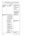
13.4

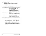
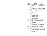
About Faults

Faults indicate conditions within the drive that require immediate 
attention. The drive responds to a fault by initiating a coast-to-stop 
sequence and turning off output power to the motor.

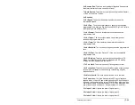
In addition, some faults are auto-resettable, non-resettable, and/or 
user-configurable as described in table 13.5.

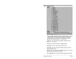
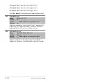
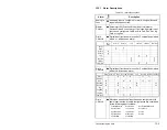
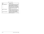
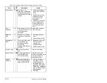
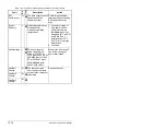
UserSet 
Conflict

Datalink ln is linked to Dyn UserSetSel (205) without the 
identical condition being present in the other two User sets. 
This alarm will occur even if the other two User Sets are 
unused.

A digital input is set to UserSetBitx without the identical 
condition being present in the other two User sets. This 
alarm will occur even if the other two User Sets are unused.

VHz Neg 
Slope

Custom V/Hz mode has been selected in Torq Perf Mode 
(53) and the V/Hz slope is negative.

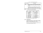
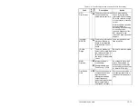
Table 13.3 – Alarm Descriptions (Continued)

Alarm

Ty

p

e

Description

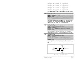
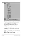
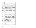
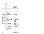
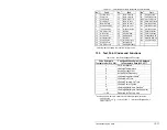
Table 13.4 – Alarm Names Cross-Referenced by Alarm Numbers

No.

1

1

Alarm numbers not listed are reserved for future use.

Alarm

No.

1

Alarm

1

Precharge Active

20

Bipolar Conflict

2

UnderVoltage

21

Motor Type Conflict

3

Power Loss

22

NP Hz Conflict

5

Analog In Loss

23

MaxFreq Conflict

6

IntDBRes OvrHeat

24

VHz Neg Slope

8

Drive OL Level 1

25

IR Volts Range

9

Drive OL Level 2

26

FluxAmps Ref Rang

17

Dig In ConflictA

27

Speed Ref Cflct

18

Dig In ConflictB

30

DigIn Bad Value

19

Dig In ConflictC

32

UserSet Conflict

Summary of Contents for Reliance electric 6SP201-015

Page 1: ...Instruction Manual SP600 AC Drive User Manual Version 2 0 0 5 to 10 HP 230 VAC 0 5 to 50 HP 460 VAC 0 5 to 20 HP 600 VAC D2 3485 4 NEMA 4X 12 NEMA 1 ...

Page 2: ... voltmeter to ensure the DC bus capacitors are discharged before touching any internal components Failure to observe this precaution could result in severe bodily injury or loss of life ATTENTION The drive can operate at and maintain zero speed The user is responsible for assuring safe conditions for operating personnel by providing suitable guards audible or visual alarms or other devices to indi...

Page 3: ...meter MOP Function 2 9 2 4 10Auto Restart Reset Run 2 9 2 4 11Autotune 2 10 2 4 12Drive Protection Current Limit 2 11 2 4 13Drive Overload Protection 2 11 2 4 14Motor Overload Protection 2 12 2 4 15Shear Pin Fault 2 12 2 4 16Drive Peripheral Interface DPI 2 12 2 4 17Network Data Transfer via Datalinks 2 12 2 4 18Programmable Parameter Access Levels and Protection 2 13 2 4 19User Sets 2 13 2 4 19 1...

Page 4: ...tactors 4 4 4 2 Control and Signal Wire 4 5 4 3 Recommended Motor Lead Lengths 4 5 4 3 1 Reflected Wave Compensation 4 7 4 4 Selecting Input Line Branch Circuit Protection 4 9 Chapter 5 Finding Wire Routing Locations and Grounding the Drive 5 1 Routing Input Motor Output Ground and Control Wiring for the Drive 5 1 5 2 Grounding the Drive 5 3 Chapter 6 Installing Power Wiring 6 1 Removing and Repla...

Page 5: ... 1 Key Descriptions 9 4 9 4 LCD OIM Menu Structure 9 5 9 5 Powering Up and Adjusting the LCD OIM 9 6 9 5 1 Selecting the Fast Power Up Feature 9 6 9 5 2 Adjusting the Screen Contrast 9 6 9 5 3 Resetting the Display 9 6 9 6 Selecting a Device in the System 9 6 9 7 Using the LCD OIM to Program the Drive 9 6 9 7 1 Viewing and Adjusting Parameters 9 7 9 7 2 Loading and Saving User Sets 9 8 9 8 Monitor...

Page 6: ... Other Parameter Levels 11 6 11 4Using the Write Protect Password to Ensure Program Security 11 7 Chapter 12 Parameter Descriptions Chapter 13 Troubleshooting the Drive 13 1Verifying that DC Bus Capacitors are Discharged Before Servicing the Drive 13 1 13 2Determining Drive Status Using the Ready LED 13 3 13 3About Alarms 13 4 13 3 1Alarm Descriptions 13 5 13 4About Faults 13 7 13 4 1About the Fau...

Page 7: ...3 13 Figure 3 12 D Frame Flange Mount Cutout Dimensions 3 14 Figure 3 13 E Frame Flange Mount Cutout Dimensions 3 14 Figure 4 1 How to Calculate Motor Lead Lengths 4 6 Figure 4 2 Inverter and Motor Line to line Voltages 4 7 Figure 4 3 Motor Overvoltage as a Function of Cable Length 4 8 Figure 5 1 Typical Wire Routing and Terminal Block Locations 5 HP Drive Shown 5 2 Figure 5 2 Typical Grounding 5 ...

Page 8: ...t Up Routines 10 2 Figure 10 2 Start Up Menu 10 2 Figure 10 3 Start Stop Control using the Local OIM 10 5 Figure 10 4 Two Wire and Three Wire Start Stop Control 10 6 Figure 10 5 Analog Speed Reference 10 6 Figure 11 1 Example of Parameter Organization 11 2 Figure 11 2 Accessing the Parameters Using the LCD OIM 11 3 Figure 11 3 Parameter Access Levels 11 5 Figure 11 4 Selecting the Parameter Access...

Page 9: ...ig In Status 216 12 65 Figure 12 36 Dig Out Status 217 12 66 Figure 12 37 Status 1 Fault 227 12 68 Figure 12 38 Status 2 Fault 228 12 68 Figure 12 39 Alarm 1 Fault 229 12 69 Figure 12 40 Alarm 2 Fault 230 12 69 Figure 12 41 Fault Config 1 238 12 71 Figure 12 42 Alarm Config 1 259 12 72 Figure 12 43 Drive Logic Rslt 271 12 73 Figure 12 44 Manual Mask 286 12 74 Figure 12 45 Stop Owner 12 75 Figure 1...

Page 10: ... Figure 13 8 Accessing the List of Changed Parameters 13 25 Figure 13 9 Accessing the Device Version Information 13 26 Figure 13 10 Device Version Screens at Product and Component Levels 13 26 Figure 13 11 Accessing the OIM Version Information 13 27 Figure 13 12 OIM Version Screens at the Product and Component Levels 13 27 Figure 13 13 Accessing the Device Item Information 13 27 ...

Page 11: ...nal Block Specifications 4 3 Table 4 3 Recommended Signal and Control Wire 4 5 Table 4 4 I O Terminal Block Specifications 4 5 Table 4 5 SP600 208 240 VAC Input Recommended Protection Devices 4 10 Table 4 6 SP600 400 480 VAC Input Recommended Protection Devices 4 11 Table 4 7 SP600 600 VAC Input Recommended Protection Devices 4 12 Table 6 1 Terminal Tightening Torques 6 5 Table 6 2 AC Line Reactor...

Page 12: ...ions and Corrective Actions 13 11 Table 13 7 Fault Names Cross Referenced by Fault Number 13 17 Table 13 8 Test Point Codes and Functions 13 17 Table 13 9 Drive Does Not Start From Start Run or Jog Inputs Wired to the Terminal Block 13 18 Table 13 10 Drive Does Not Start or Jog From OIM 13 19 Table 13 11 Drive Does Not Respond to Changes in Speed Command 13 20 Table 13 12 Drive Does Not Operate in...

Page 13: ...st instances parameter names are shown as the parameter name followed by the parameter number For example PI Control 125 1 2 Getting Assistance from Reliance Electric If you have any questions or problems with the products described in this instruction manual contact your local Reliance Electric sales office For technical assistance call 1 864 284 5444 Before calling please review the troubleshoot...

Page 14: ...1 2 SP600 AC Drive User Manual ...

Page 15: ...gulation for a broad range of applications requiring adjustable speed control of motors This chapter provides information about the SP600 AC drive including Information on identifying the drive Descriptions of NEMA ratings Descriptions of features Information on CE filters and requirements for CE compliance A description of drive connections and communication options ...

Page 16: ... 2 A 0 5 HP 0 37 kW 4P2 4 2 A 1 0 HP 0 75 kW 6P8 6 8 A 2 0 HP 1 5 kW 9P6 9 6 A 3 0 HP 2 2 kW 015 15 3 A 5 0 HP 4 0 kW 022 22 0 A 7 5 HP 5 5 kW 028 28 0 A 10 0 HP 7 5 kW 480 VAC 600 VAC 1P1 1 1 A 0 5 HP 0 37 kW 0P9 0 9 A 0 5 HP 0 37 kW 2P1 2 1 A 1 0 HP 0 75 kW 1P7 1 7 A 1 0 HP 0 75 kW 3P4 3 4 A 2 0 HP 1 5 kW 2P7 2 7 A 2 0 HP 1 5 kW 005 5 0 A 3 0 HP 2 2 kW 3P9 3 9 A 3 0 HP 2 2 kW 008 8 0 A 5 0 HP 4 ...

Page 17: ...indoor environments that require a dust tight and drip tight corrosion resistant enclosure IP66 Dust tight and protected against heavy jet spray NEMA 12 Dust tight and drip tight Tables 2 3 2 4 and 2 5 list the drives and their power ratings Table 2 1 Identifying the NEMA 1 Drive by Frame Frame 240 V 400 V 480 V 600 V A1 1 Note these ratings with internal filters are shipped as a B size frame 5 1 ...

Page 18: ...240 VAC 208 VAC 240 VAC Cont 1 min 3 sec Cont 1 min 3 sec 6SP2yz 2P2xxxx 0 5 0 37 0 33 0 25 1 1 1 2 2 9 2 5 2 5 2 7 3 7 2 2 2 4 3 3 45 6SP2yz 4P2xxxx 1 0 0 75 0 75 0 55 2 0 2 3 5 6 4 8 4 8 5 5 7 4 4 2 4 8 6 4 68 6SP2yz 6P8xxxx 2 0 1 5 1 5 1 1 3 6 4 2 10 0 8 7 7 8 10 3 13 8 6 8 9 0 12 0 88 6SP2yz 9P6xxxx 3 0 2 2 2 0 1 5 5 1 5 8 14 0 12 2 11 0 12 1 16 5 9 6 10 6 14 4 130 6SP2yz 015xxxx 5 0 4 0 3 0 3...

Page 19: ...2 57 6SP4yz 3P4xxxx 2 0 1 5 1 5 1 1 3 0 3 2 4 3 3 8 3 5 4 5 6 3 4 4 5 6 0 79 6SP4yz 005xxxx 3 0 2 2 2 1 5 4 5 4 7 6 5 5 6 5 0 5 5 7 5 5 0 5 5 7 5 102 6SP4yz 008xxxx 5 0 4 3 2 2 8 4 8 4 11 3 9 8 8 7 9 9 13 2 8 0 8 8 12 141 6SP4yz 011xxxx 7 5 5 5 5 4 0 7 9 7 9 10 5 9 4 11 5 13 17 4 11 12 1 16 5 175 6SP4yz 014xxxx 10 7 5 7 5 5 5 10 4 10 4 14 1 12 4 15 4 17 2 23 1 14 16 5 22 235 6SP4yz 022xxxx 15 11 1...

Page 20: ...0 OL Duty 150 OL Duty 600 VAC Input HP kW HP kW Cont 1 min 3 sec 6SP5yz 0P9xxx 0 5 0 37 0 33 0 25 1 3 1 3 0 9 1 0 1 4 44 6SP5yz 1P7xxxx 1 0 75 0 75 0 50 2 0 1 9 1 7 2 0 2 6 57 6SP5yz 2P7xxxx 2 1 5 1 5 1 0 3 1 3 0 2 7 3 6 4 8 79 6SP5yz 3P9xxxx 3 2 2 2 1 5 4 5 4 4 3 9 4 3 5 8 102 6SP5yz 6P1xxxx 5 4 3 2 0 7 8 7 5 6 1 6 7 9 1 140 6SP5yz 9P0xxxx 7 5 5 5 5 3 75 8 0 7 7 9 9 9 13 5 175 6SP5yz 011xxxx 10 7...

Page 21: ...urrent limit and DC braking level Current Limit Sel 147 and DC Brake Lvl Sel 157 Refer to the parameter descriptions in chapter 12 for more information about configuring the analog inputs 2 4 2 Analog Output The drive has one analog output that can be used as a voltage signal 0 to 10 V to annunciate a wide variety of drive operating conditions and values Select the source for the analog output by ...

Page 22: ...t these stop mode selections Another stop method dynamic braking uses an optional internal or external DB braking resistor to dissipate stopping energy See parameters 161 to 163 for more information about this feature 2 4 6 Multiple Speed Control Methods The purpose of speed regulation is to allow the drive to adjust to certain operating conditions such as load change and compensate for these chan...

Page 23: ...er MOP Function The Motor Operated Pot MOP function is one of the sources for the frequency reference selected in parameter 90 The MOP function uses digital inputs to increment or decrement the speed reference at a programmed rate The MOP has these components MOP Rate parameter 195 Save MOP Ref parameter 194 MOP Frequency parameter 11 MOP increment input parameters 361 to 366 MOP decrement input p...

Page 24: ...the dynamic Autotune procedure determines both the stator resistance and motor flux current IR Voltage Drop 62 is used by the drive to provide additional voltage at all frequencies to offset the voltage drop developed across the stator resistance An accurate calculation of the IR Voltage Drop will ensure higher starting torque and better performance at low speed operation If it is not possible or ...

Page 25: ...s the temperature of the power module based on a measured temperature and a thermal model of the IGBT As the temperature rises the drive may lower the PWM frequency to decrease the switching losses in the IGBT If the temperature continues to rise the drive may reduce current limit to try to decrease the load on the drive If the drive temperature becomes critical the drive generates a fault If the ...

Page 26: ...u want to stop the process in the event of excess current the Shear Pin feature can be activated By programming the drive current limit value and enabling the electronic shear pin the drive will fault if excess current is demanded by the motor 2 4 16 Drive Peripheral Interface DPI SP600 drives support Drive Peripheral Interface DPI communication protocols for the primary interface and drive contro...

Page 27: ... password See section 11 3 5 for more information about this password You can also protect parameters from unauthorized changes by activating the Write Protect password See section 11 4 for more information about this password 2 4 19 User Sets 2 4 19 1Normal Mode After a drive has been configured for a given application you can store a copy of all of the parameter settings in a specific EEPROM are...

Page 28: ...of User Sets from the drive s Terminal Block Up to two digital inputs can be defined to allow selection of any combination of the three User Sets Digital Inputs can be configured through Parameters 361 through 366 The Dynamic Mode Operation User Set operation is enabled and disabled by a configuration parameter 204 Important Parameter writes are only recorded in the operating memory and not copied...

Page 29: ...aded Repeat step 2 Step 4 Begin normal drive operation Remember that User Sets can only be loaded while the drive is stopped At power up the drive will load operating memory with the values contained in the active non volatile storage as part of initialization If Dynamic Mode is Enabled the selected User Set data will be loaded and processed after drive initialization completes but before the driv...

Page 30: ...more information 2 4 21 S Curve The S Curve function of SP600 drives allows control of the jerk component of acceleration and deceleration through adjustment of the S Curve parameter 146 Jerk is defined as the rate of change of acceleration and or deceleration By adjusting the percentage of the S Curve applied to the normal accel decel ramps the ramp takes the shape of an S allowing a smoother tra...

Page 31: ...ngs will change In most cases all drives within a voltage class can be reprogrammed to accommodate a motor within its voltage class This can be done by resetting the Voltage Class parameter 202 to a different setup within the voltage class As an example consider a 480 volt drive This drive comes with factory default values for 480 V 60 Hz with motor data defaulted for U S motors HP rated 1750 RPM ...

Page 32: ...etween frequency and voltage is a square function where the voltage is proportional to frequency The fan curve provides the option to generate voltage that is a function of the stator frequency squared up to the motor nameplate frequency Above base frequency the voltage is a linear function of frequency At low speed the fan curve can be offset by the Run Boost 70 parameter to provide necessary sta...

Page 33: ...n and top openings less than 1 0 mm 0 04 in to maintain compliance with the Low Voltage Directive Conformity with CE EMC requirements does not guarantee that the entire machine or installation will comply with the requirements Many factors can influence total machine installation compliance Use of line filters in ungrounded systems is not recommended SP600 drives can generate conducted low frequen...

Page 34: ...ption External Filter Input Ferrite2 2 Input cables through a Ferrite Core Frames A B and C Fair Rite 2643102002 or equivalent Frame D Fair Rite 2643251002 or equivalent A Drive Only with any Comm Option with ControlNet B Drive Only with any Comm Option with ControlNet C Drive Only with any Comm Option with ControlNet D Drive Only with any Comm Option with ControlNet E Drive Only with any Comm Opt...

Page 35: ...ote OIM or VS Utilities DPI Port 3 Cable connection for remote OIM or VS Utilities DPI Port 5 Connection for an optional communications module Power Terminal Block Connections for input and output power wiring Signal and I O Terminal Block Connections for signal and I O wiring Figure 2 4 Drive Connections NEMA 1 Drives 2 1or3 COMM PORT CTRL BD GND UIB CONN CONTROL POWER CONN WIRE STRIP CONTROL POW...

Page 36: ...n the NEMA 1 drive No Connector Description DPI Port 2 Cable connection for remote OIM or VS Utilities DPI Port 3 Cable connection for remote OIM or VS Utilities DPI Port 5 Connection for an optional communications module Signal and I O Terminal Block Connections for signal and I O wiring Power Terminal Block Connections for input and output power wiring Figure 2 5 Drive Connections NEMA 4 Drives ...

Page 37: ...l from the remote keypad 2 8 1 Connecting the Remote OIM or VS Utilities to the Drive NEMA 1 Drives The remote OIM or VS Utilities via the Serial Converter see section 2 10 connects to DPI port 2 at the bottom of the drive frame labeled in figure 2 4 Table 2 7 Communication Options Model Numbers and Instruction Manual Numbers Description Model Number Instruction Manual DeviceNet Communication Modu...

Page 38: ... Based Utility The SP600 drive can be configured using a PC based software utility such as VS Utilities This program enables you to upload and download parameter configurations Figure 2 6 DPI Port 2 on NEMA 4 Drives Table 2 9 PC Based Utility Model Number and Instruction Manual Number Description Model Number Instruction Manual VS Utilities RECOMM VSU232 D2 3488 Serial Converter for DPI Drives inc...

Page 39: ... the output of the drive can result in erratic operation of the motor nuisance tripping and or permanent damage to the drive Remove power correction capacitors before proceeding Failure to observe this precaution could result in damage to or destruction of the equipment ATTENTION The user is responsible for conforming with all applicable local national and international codes Failure to observe th...

Page 40: ...ntrol and power wiring Power connections may create electromagnetic fields that may interfere with control wiring or components when run in close proximity to the drive Read the recommendations in the following sections before continuing with drive installation 3 1 1 Verifying Power Module AC Input Ratings Match Available Power SP600 drives are suitable for use on a circuit capable of delivering u...

Page 41: ...ive is installed on an ungrounded distribution system where the line to ground voltages on any phase could exceed 125 of the nominal line to line voltage Failure to observe this precaution could result in damage to or destruction of the equipment ATTENTION To avoid electric shock hazard verify that the voltage on the bus capacitors has discharged before removing installing jumpers Measure the DC b...

Page 42: ... spikes in excess of 6000 volts These spikes could be caused by other equipment on the line or by events such as lightning strikes The power source has frequent interruptions Table 3 1 MOV and Common Mode Capacitor Jumpers Frame Jumper Removes A N A B JP6 JP5 Common Mode Capacitors to Ground C and D JP3B JP3A Common Mode Capacitors to Ground E JP3 JP4 Common Mode Capacitors to Ground DC DC Convert...

Page 43: ...n the transformer and drive or an additional transformer or reactor 3 1 2 Making Sure Environmental Conditions are Met Before deciding on an installation site consider the following guidelines Verify that NEMA 1 drives can be kept clean cool and dry The area chosen should allow the space required for proper air flow as defined in section 3 1 3 Be sure that NEMA 1 drives are away from oil coolants ...

Page 44: ... side clearance For best air movement do not mount SP600 AC drives directly above each other Note that no devices are to be mounted behind the drive This area must be kept clear of all control and power wiring See figure 3 3 for recommended air flow clearances Figure 3 3 Minimum Mounting Clearances 76 2 mm 3 0 in 76 2 mm 3 0 in 76 2 mm 3 0 in 76 2 mm 3 0 in Clearances apply to all SP600 Drives Pan...

Page 45: ...7 30 E E4 Frame1 A B C D E F Weight 2 kg lb IP20 NEMA Type 1 A 122 4 4 82 225 7 8 89 179 8 7 08 94 2 3 71 211 6 8 33 5 8 0 23 2 71 5 97 B 171 7 6 76 234 6 9 24 179 8 7 08 122 7 4 83 220 2 8 67 5 8 0 23 3 60 7 93 C 185 0 7 28 300 0 11 81 179 8 7 08 137 6 5 42 285 6 11 25 5 8 0 23 6 89 15 18 D 219 9 8 66 350 0 13 78 179 8 7 08 169 0 6 65 335 6 13 21 5 8 0 23 9 25 20 4 E 280 3 11 04 555 8 21 88 207 1...

Page 46: ...8 6 7 03 123 0 4 84 55 6 2 19 7 03 15 5 C 219 0 8 62 300 0 11 81 178 6 7 03 123 0 4 84 55 6 2 19 12 52 27 6 D 248 4 9 78 350 0 13 78 178 6 7 03 117 2 4 61 55 6 2 19 18 55 40 9 E 280 3 11 04 555 8 21 88 207 1 8 15 130 0 5 12 89 9 3 54 18 60 41 0 Figure 3 5 Flange Mount Drive Dimensions 1 See table 3 2 2 Weights include OIM and standard I O Dimensions in mm in B A C D E ...

Page 47: ...136 7 5 38 155 2 6 11 163 7 6 45 22 2 0 87 Dia 5 Places 36 1 1 42 56 1 2 21 75 2 2 96 94 2 3 71 47 7 1 88 58 4 2 30 112 3 4 42 101 3 3 99 129 3 5 09 155 2 6 11 163 5 6 44 22 2 0 87 Dia 4 Places 37 5 1 48 64 0 2 52 93 0 3 66 121 0 4 76 149 7 5 89 69 3 2 73 58 6 2 31 103 2 4 06 134 7 5 30 155 2 6 11 164 1 6 46 28 5 1 12 Dia 2 Places 22 2 0 87 Dia 2 Places Frame A Frame B Frame C Frame D Dimensions i...

Page 48: ...Dimensions in mm in 55 2 2 17 77 3 3 04 99 6 3 92 115 9 4 56 99 6 3 92 138 2 5 44 28 3 1 11 22 1 0 87 31 0 1 22 49 1 1 93 75 5 2 97 102 0 4 02 120 1 4 73 102 9 4 05 138 6 5 46 140 5 5 53 28 3 1 11 22 1 0 87 108 2 4 26 157 7 6 21 165 7 6 52 207 7 8 18 22 5 0 89 44 5 1 75 124 9 4 92 139 9 5 51 163 4 6 43 Frame E ...

Page 49: ...9 76 6 3 02 95 0 3 74 103 5 4 07 22 2 0 87 Dia 5 Places 53 1 2 09 73 0 2 87 92 2 3 63 111 2 4 38 64 7 2 55 75 4 2 97 129 3 5 09 40 6 1 60 68 7 2 70 94 6 3 72 102 9 4 05 22 2 0 87 Dia 4 Places 51 9 2 04 78 3 3 08 107 3 4 22 135 5 5 33 164 1 6 46 83 7 3 30 73 0 2 87 42 3 1 67 74 1 2 92 94 6 3 27 103 5 4 07 28 5 1 12 Dia 2 Places 22 2 0 87 Dia 2 Places Frame A Frame B Frame C Frame D Dimensions in mm...

Page 50: ...ance com website Attach the drive to the vertical surface using the mounting holes provided Panel mount drives Drives should be mounted using 10 32 bolts Use washers under the bolt heads Flange mount drives Use the fasteners supplied with the drive Figure 3 9 A Frame Flange Mount Cutout Dimensions 127 0 5 00 197 9 7 80 156 0 6 14 6 9 0 27 140 7 5 54 70 7 2 78 210 6 8 29 225 8 8 89 105 3 4 15 5 0 0...

Page 51: ...imensions 176 3 6 94 205 5 8 09 205 2 8 08 6 9 0 27 190 0 7 48 95 0 3 74 219 3 8 63 234 6 9 24 109 7 4 32 6 9 0 27 8x 3 5 0 14 4x 3 0R 0 12R 58 8 2 31 189 4 7 46 272 3 10 72 219 0 8 62 6 3 0 25 202 0 7 95 101 0 3 98 283 0 11 14 300 0 11 81 41 5 1 63 141 5 5 57 241 5 9 51 5 1 0 20 12x 3 5 0 14 4x 3 0R 0 12R 58 8 2 31 ...

Page 52: ... 0 13 11 350 0 13 78 61 5 2 42 201 5 7 93 131 5 5 18 271 5 10 69 4 5 0 18 14x 3 5 0 14 4x 3 0R 0 12R 58 8 2 31 Figure 3 13 E Frame Flange Mount Cutout Dimensions 250 4 9 86 525 8 20 70 280 3 11 04 6 0 0 24 131 2 5 16 206 2 8 12 262 4 10 33 56 2 2 21 493 9 19 44 555 8 21 88 193 9 7 63 118 9 4 68 43 9 1 73 343 9 13 54 268 9 10 59 418 9 16 49 6 0 0 24 20x 3 5 0 14 87 1 3 43 ...

Page 53: ...mine the watts loss rating of the drive from tables 2 4 through 2 6 These tables list the typical full load power loss watts value 4 kHz carrier frequency Ensure that the enclosure is adequately ventilated and the ambient air is within the specified temperature range NEMA 1 0 to 50 C 32 to 122 F NEMA 4X 0 to 40 C 32 to 104 F ...

Page 54: ...Mounting the Drive 3 16 ...

Page 55: ...s an approximate guide allow a spacing of 0 3 meters 1 foot for every 10 meters 32 8 feet of length In all cases long parallel runs must be avoided Do not use cable with an insulation thickness less than or equal to 15 mils 0 4 mm 0 015 in See table 4 1 ATTENTION The user is responsible for conforming with all applicable local national and international codes Failure to observe this precaution cou...

Page 56: ...creased impedance of shielded cable may help extend the distance that the motor can be located from the drive without the addition of motor protective devices such as terminator networks Consideration should be given to all of the general specifications dictated by the environment of the installation including temperature flexibility moisture characteristics and chemical resistance In addition a b...

Page 57: ...LF 7xxxxx or equivalent Three tinned copper conductors with XLPE insulation 5 mil single helical copper tape 25 overlap min with three bare copper grounds in contact with shield PVC jacket Class I II Division I II Tray rated 600V 90 C 194 F RHH RHW 2 Anixter 7V 7xxxx 3G or equivalent Three bare copper conductors with XLPE insulation and impervious corrugated continuously welded aluminum armor Blac...

Page 58: ...en the drive and motor s for the purpose of disconnecting or isolating certain motors loads If a contactor is opened while the drive is operating power will be removed from the respective motor but the drive will continue to produce voltage at the output terminals Disconnecting a motor under load can cause damage to the contactor as well as the drive because the DV DT change in voltage Change in t...

Page 59: ...ntrol Wire Signal Type Wire Type s Description Minimum Insulation Rating Analog I O Belden 8760 9460 or equiv 0 750 mm2 18 AWG twisted pair 100 shield with drain1 300V 75 90 C 167 194 F Belden 8770 or equiv 0 750 mm2 18 AWG 3 conductor shielded for remote pot only Unshielded Control Per US NEC or applicable national or local code 300V 60 C 140 F Shielded Control Multi conductor shielded cable such...

Page 60: ... restricted to a shorter lead length due to the type of wire shielded or unshielded the placement of wire for example in conduit or a cable tray the type of line reactor the type of motor voltage class 1000 V 1200 V or 1600 V carrier frequency Figure 4 1 illustrates how to calculate motor lead lengths The examples shown assume a maximum lead length of 200 feet Motor lead lengths in excess of 200 f...

Page 61: ...he correction software modifies the PWM modulator to prevent PWM pulses less than a minimum time from being applied to the motor The minimum time between PWM pulses is 10 microseconds The modifications to the PWM modulator limit the overvoltage transient to 2 25 per unit volts line to line peak at 600 feet of cable 400 V Line 540V DC bus max x 2 25 1200 V 480 V Line 715V DC bus max x 2 25 1600 V 6...

Page 62: ...s the per unit motor overvoltage as a function of cable length This is for no correction versus the modulation correction code for varied lengths of 12 AWG PVC cable to 600 feet for a 4 kHz and 8 kHz carrier frequencies The output line to line voltage was measured at the motor terminals in 100 feet increments Without the correction the overvoltage increases to unsafe levels with increasing cable l...

Page 63: ...recommended types listed below If available amp ratings do not match the tables provided the closest fuse rating that exceeds the drive rating should be chosen IEC BS88 British Standard Parts 1 21 EN60269 1 Parts 1 2 type gG or equivalent should be used UL UL Class CC T or J must be used 2 Circuit Breakers The circuit breakers listed in tables 4 5 through 4 7 are for inverse time circuit breakers ...

Page 64: ...0 5 0 33 4 4 5 6 8 15 6SP201 4P2 1 0 75 6 9 10 15 15 6SP201 6P8 2 1 5 15 15 15 25 25 6SP201 9P6 3 2 20 20 20 35 35 6SP201 015 5 3 20 30 20 60 60 6SP201 022 7 5 5 25 45 25 80 80 6SP201 028 10 7 5 35 60 35 110 110 1 Circuit Breaker inverse time breaker For US NEC minimum size is 125 of motor FLA Ratings shown are maximum 2 Minimum protection device size is the lowest rated device that supplies maxim...

Page 65: ...eaker1 ND HD Min2 Max3 Min2 Max3 Max4 480 VAC Input 6SP401 1P1 0 5 0 33 3 3 3 4 15 6SP401 2P1 1 0 75 6 6 3 8 15 6SP401 3P4 2 1 5 6 6 6 12 15 6SP401 005 3 2 10 10 10 20 20 6SP401 008 5 3 15 15 15 30 30 6SP401 011 7 5 5 15 20 15 40 40 6SP401 014 10 7 5 20 30 20 50 50 6SP401 022 15 10 25 45 25 80 80 6SP401 027 20 15 35 60 35 100 100 6SP401 034 25 20 40 70 40 125 125 6SP401 040 30 25 50 90 50 150 150 ...

Page 66: ...rotection without nuisance tripping Max3 Min2 Max3 3 Maximum protection device size is the highest rated device that supplies drive protection For US NEC minimum size is 125 of motor FLA Ratings shown are maximum Max4 4 Maximum allowable rating by US NEC Exact size must be chosen for each installation 6SP501 0P9 0 5 0 33 3 3 3 3 5 15 6SP501 1P7 1 0 75 3 6 3 6 15 6SP501 2P7 2 1 5 4 6 4 10 15 6SP501...

Page 67: ...re chafing Figure 5 1 shows the wire routing grounding terminal and power terminal blocks of the SP600 AC drives Do not route more than three sets of motor leads through a single conduit This will minimize cross talk that could reduce the effectiveness of noise reduction methods If more than three drive motor connections per conduit are required shielded cable must be used If possible each conduit...

Page 68: ...ives using this conduit should be disabled to eliminate the possible shock hazard from cross coupled motor leads Failure to observe these precautions could result in bodily injury Power Terminal Block SHLD Terminal Suggested entry for incoming line wiring Suggested entry for motor wiring I O Terminal Block Signal and Control Suggested entry for communication wiring Suggested entry for I O and cont...

Page 69: ...a single safety ground point or ground bus bar connected directly to building steel should be used All circuits including the AC input ground conductor should be grounded independently and directly to this point bar ATTENTION The user is responsible for conforming with all applicable local national and international codes Failure to observe this precaution could result in damage to or destruction ...

Page 70: ...g cable gland may so be used When shielded cable is used for control and signal wiring the shield should be grounded at the source end only not at the drive end RFI Filter Grounding Using an optional RFI filter may result in relatively high ground leakage currents Therefore the filter must only be used in installations with grounded AC supply systems and be permanently installed and solidly ground...

Page 71: ...2 Lift the cover straight off the drive to avoid damaging the connector pins ATTENTION The user is responsible for conforming with all applicable local and national codes Failure to observe this precaution could result in damage to or destruction of the equipment ATTENTION DC bus capacitors retain hazardous voltages after input power has been removed After disconnecting input power wait five minut...

Page 72: ...Replacing the Cover on NEMA 4x 12 Drives Removing the Cover Follow these steps to remove the drive cover on NEMA 4x 12 drives Step 1 Remove any user supplied locks from the drive Step 2 Loosen the four cover screws refer to figure 6 2 Frame E has a total of 10 screws that need to be loosened Step 3 Lift the cover straight off the drive to avoid damaging the connector pins Figure 6 1 Removing the D...

Page 73: ...additional locks Refer to section 6 1 2 1 Locking the Cover Important Use the plugs supplied with IP66 NEMA 4X 12 rated drives to seal unused holes in the conduit entry plate Completely seat the plug inner rim for the best seal See figure 6 3 Figure 6 2 Removing the Drive Cover NEMA 4x 12 Drives Frames B4 and D4 shown ATTENTION Mount the front cover and bottom cover carefully to avoid damaging the...

Page 74: ...EMA 4x 12 SP600 drive provides two sets of slots for use with user supplied locks Refer to figure 6 4 Figure 6 3 Installing Plugs in Unused Holes in Conduit Entry Plate on NEMA 4X 12 Drives Figure 6 4 Location of Slots for User Supplied Locks on NEMA 4x 12 Drives ...

Page 75: ...k See figure 6 5 Step 3 Tighten the three phase AC output power terminals to the proper torque according to drive type as shown in table 6 1 ATTENTION Donotroutesignalandcontrolwiringwithpower wiring in the same conduit This can cause interference with drive operation Failure to observe these precautions could result in damage to or destruction of the equipment ATTENTION Unused wires in conduit mu...

Page 76: ...e primary of the transformer If the user installed power disconnecting device is a circuit breaker the circuit breaker trip rating must be coordinated with the in rush current 10 to 12 times full load current of the transformer Do not use an input isolation transformer rated more than 1000 KVA for 480 600 VAC 500 KVA for 208 VAC with less than 5 impedance directly ahead of the drive without additi...

Page 77: ...put Line to the Drive s Power Terminals To connect AC input power to the drive Step 1 Wire the AC input power leads by routing them according to drive type Refer to figure 5 1 Maximum power wiring sizes are listed in table 4 2 Step 2 Connect the three phase AC input power leads to the appropriate terminals Connect the AC input power leads to terminals R L1 S L2 T L3 on the power terminal block Ste...

Page 78: ... resistor connection U U T1 To motor V V T2 To motor W W T3 To motor PE PE Ground PE PE Ground DC DC Bus May be located to the left or right of the Power Terminal Block Figure 6 5 Power Terminal Block L1 R L2 S L3 T BR1 DC BR2 BRK T1 U T2 V T3 W PE PE DC DC Frames A D Power Terminal Block and DC Bus Test Points L1 R L2 S L3 T DC DC BR1 BR2 T1 U T2 V T3 W Frame E Power Terminal Block Figure 6 6 Pow...

Page 79: ...C bus or isolating the resistor from the DC bus It is important to properly size the braking resistor value To determine the minimum resistance value possible based on drive rating see table 6 3 Note that the resistor wattage is application dependent and should be sized to inertia deceleration and duty cycle requirements Figure 6 7 shows a simplified dynamic braking schematic Figure 6 7 Simplified...

Page 80: ...N AC drives do not offer protection for externally mounted braking resistors A risk of fire exists if external braking resistors are not protected External resistor packages must be self protected from overtemperature or the protective circuit shown in figure 6 8 or an equivalent must be supplied ATTENTION Equipment damage may result if a drive mounted internal resistor is installed and parameter ...

Page 81: ...2 306 1 85 247 400 480 V 2 HP 1 5 790 61 72 163 3 48 232 400 480 V 3 HP 2 2 790 61 72 131 4 33 197 400 480 V 5 HP 4 790 61 72 97 5 85 146 400 480 V 7 5 HP 5 5 790 66 95 70 8 11 147 400 480 V 10 HP 7 5 790 66 95 73 7 77 104 400 480 V 15 HP 11 790 39 90 45 12 61 115 400 480 V 20 HP 15 790 27 82 45 12 61 84 400 480 V 25 HP 19 790 27 33 30 18 91 101 400 480 V 30 HP 22 790 27 89 30 18 91 84 400 480 V 4...

Page 82: ...6 12 SP600 AC Drive User Manual ...

Page 83: ...rs until the motor comes to a stop and then turns off the power devices In addition to the operational stop you must provide a hardwired emergency stop external to the drive The emergency stop circuit must contain only hardwired electromechanical components Operation of the emergency stop must not depend on electronic logic hardware or software or on the communication of commands over an electroni...

Page 84: ...of 600 V or greater is recommended Control and signal wires should be separated from power wires by at least 0 3 meters 1 foot Important I O terminals labeled or Common are not referenced to earth ground and are designed to greatly reduce common mode interference Grounding these terminals can cause signal noise Wire the drive s signal and control I O to the terminal block as shown in table 7 1 ATT...

Page 85: ... VAC 30 VDC 50 VAC 60 Watts Minimum DC Load 10 µA 10 mV DC Max Inductive Load 250 VAC 30 DC 25 VAC 30 Watts 380 387 12 Digital Out 1 Common1 13 Digital Out 1 N C Fault 14 Analog In 1 Volts 2 Voltage Reads value at 14 15 Non isolated 0 to 10V 10 bit 100k ohm input impedance 3 320 327 15 Analog In 1 Volts 16 Analog In 1 Current Non isolated 4 20mA 10 bit 100 ohm input impedance 3 17 Analog In 1 Curr...

Page 86: ...r other functions will energize only when that condition exists and will deenergize when condition is removed 2 These inputs outputs are dependent on a number of parameters See Related Parameters 3 Differential Isolation External source must be less than 10V with respect to PE 4 Differential Isolation External source must be maintained at less than 160V with respect to PE Input provides high commo...

Page 87: ... 10k Ohm Pot Recommended 2k Ohm minimum Select Speed Reference source Param 090 1 Analog In 1 Adjust Scaling Param 091 092 322 323 Check Results Param 016 Joystick Bipolar Speed Reference 10V Input Set Direction Mode Param 190 1 Bipolar Adjust Scaling Param 091 092 325 326 Check Results Param 017 Analog Input Bipolar Speed Reference 10V Input Adjust Scaling Param 091 092 325 326 Check Results Para...

Page 88: ...ersing External Supply Set Digital Input 1 Param 361 9 Run Reverse Set Digital Input 2 Param 362 8 Run Forward 3 Wire Control Internal Supply Use factory default parameter settings 3 Wire Control External Supply Use factory default parameter settings Digital Output Form C Relays Energized in Normal State Select Source Param 380 384 Table 7 2 I O Wiring Examples Continued Input Output Connection Ex...

Page 89: ...2 to optional remote OIM POWER SECTION MOTOR AC INPUT 380 480 VAC T3 T2 T1 2 1 3 5 4 6 8 7 12 10 9 11 13 15 14 16 17 18 19 21 20 23 22 24 25 26 STOP CLEAR FAULTS 361 START 362 JOG 364 MANUAL 365 FUNCTION LOSS 363 24V COM LOGIC COMMON 24VDC FAULT RUN ANALOG INPUT 1 MAIN CONTROL BOARD 10VDC 0 10VDC 4 20MA ANALOG INPUT 1 0 10VDC INPUT 2 ANALOG INPUT 2 ANALOG 4 20MA OUTPUT ANALOG SPEED SEL 1 366 FUNCT...

Page 90: ...Ref A Lo 0 Hz 0 0 Hz 96 TB Man Ref Anlg 2 Anlg 2 97 TB Man Ref Hi 60 Hz Same as Max Speed 98 TB Man Ref Lo 0 Hz 0 0 Hz 320 Analog Conf xxx xx01 xxx xx01 322 Anlg In 1 Hi 20 mA 20 mA 323 Anlg In 1 Lo 4 mA 4 mA 325 Anlg In 2 Hi 10 V 10 V 326 Anlg In 2 Lo 0 V 0 V 361 Dig In 1 Sel Stop Stop 362 Dig In 2 Sel Start Start 363 Dig In 3 Sel Function Loss Function Loss 364 Dig In 4 Sel Jog Jog 365 Dig In 5 ...

Page 91: ... DPI port 2 to optional remote OIM POWER SECTION MOTOR AC INPUT 380 480 VAC T3 T2 T1 2 1 3 5 4 6 8 7 12 10 9 11 13 15 14 16 17 18 19 21 20 23 22 24 25 26 STOP CLEAR FAULTS START JOG 364 AUTORUN FUNCTION LOSS 24V COM DIGITAL INPUT COMMON 24VDC FAULT RUN ANALOG INPUT 1 MAIN CONTROL BOARD 10VDC 0 10VDC 4 20MA ANALOG INPUT 1 0 10VDC INPUT 2 ANALOG INPUT 2 ANALOG 4 20MA OUTPUT ANALOG SPEED SEL 1 FUNCTI...

Page 92: ...ic inputs are configured as a speed select source the speed reference source is channeled to Speed Ref A Sel 90 7 5 2 Manual Reference Sources The manual reference source can be provided by the terminal block an OIM connected to the local port remote OIM port 2 or 3 the network port The manual reference overrides any auto reference selected By configuring the LCD OIM s function keys an LCD OIM can...

Page 93: ... have to be switched to Auto and then back to Manual to re acquire Manual reference control The Jog reference will bypass the Auto Manual reference while it is asserted from the control source When the Jog reference is released the control source reverts to the source that was in effect before the Jog reference was asserted Figure 7 3 Speed Reference Control Flowchart Preset Speed 1 Parameter 101 ...

Page 94: ...a remote OIM is connected as the user interface for speed reference or logic control Logic Source Sel 89 and Speed Ref A Select 90 must be configured for the connection port to which the remote OIM is attached Typically a remote OIM is connected to port 2 or port 3 ...

Page 95: ...Speed 1 Preset Speed 2 Preset Speed 3 Preset Speed 4 Preset Speed 5 Preset Speed 6 Preset Speed 7 PI output Speed Mode PI Configuration Speed Mode Process PI PI Configuration Excl Mode and PI is enabled Jog Speed Jogging Commanded Freq Auto DPI Port 2 Ref Preset Speed 1 Preset Speed 2 Preset Speed 7 LCD OIM Function Keys DPI Port 3 Ref Preset Speed 1 Preset Speed 2 Preset Speed 7 Network Port Ref ...

Page 96: ...7 14 SP600 AC Drive User Manual ...

Page 97: ...th the construction and operation of this equipment and the hazards involved should start and adjust it Read and understand this manual in its entirety before proceeding Failure to observe this precaution could result in severe bodily injury or loss of life ATTENTION DC bus capacitors retain hazardous voltages after input power has been disconnected After disconnecting input power wait five minute...

Page 98: ...ween the drive and the motor Step 13 Check that the rating of the transformer if used matches the drive requirements and is connected properly Step 14 Verify that a properly sized ground wire is installed and a suitable earth ground is used Check for and eliminate any grounds between the motor frame and the motor power leads Verify that all ground leads are unbroken Step 15 Uncouple the motor from...

Page 99: ...sing extender cables Connect the cable to either DPI port 2 or 3 Remote mounted A NEMA 4 remote mount OIM is available or a cable RECBL LCD can be used to convert the standard OIM for remote mounted use NEMA 1 drives only The maximum cable length is 32 feet using extender cables Connect the cable to either DPI port 2 or 3 See figure 2 2 in chapter 2 for the connection points on the drive Figure 9 ...

Page 100: ...ed by the OIM If the local LCD OIM is not the selected control source or reference source removing the OIM while the drive is powered will have no effect on drive operation Figure 9 2 Installing and Removing the Local LCD OIM NEMA 1 Only text F1 ESC PROG JOG F2 F3 F4 o I ATTENTION RemovingandreplacingtheLCDOIM while the driveis runningmaycause an abruptspeed change if the LCD OIM is the selected r...

Page 101: ...r example Running Stopped etc Alarm annunciation Alarm has occurred Auto Manual mode status Write protect password status unlocked password disabled locked password enabled See section 11 4 Figure 9 3 The Display Main Menu Shown P0 SP600 Auto Stopped Main Menu Start Up Operational Status Line Device Selected Error Text Function Key Line Lang Menu Programming Screen or Process User Display Command ...

Page 102: ...y screens Enter a menu select an option or save changes to parameter value Change motor direction if the OIM is the control source Jog the drive if the OIM is the control source Stop the drive Clear a fault if the OIM is the control source Start the drive if the OIM is the control source F1 though F4 Predefined or user configured functions The definition of each key is shown directly above the key...

Page 103: ...W Set Acc Lvl PW Set Access Lvl QuickStart Motor Data Configure I O Ref Setup Speed Limits Input Voltage Motor Tests Done ESC PROG Logout Menu options dependent upon devices connected OIM Version Device Version View Fault Queue Device Items Status Info Fault Info Tech Support ESC PROG Refer to section 9 8 Refer to chapter 10 Refer to chapter 11 Refer to section 9 9 Refer to section 13 8 Refer to s...

Page 104: ...splay menu 9 5 3 Resetting the Display To return all the options for the display to factory default values select Reset Display from the Display menu 9 6 Selecting a Device in the System The LCD OIM can access and display data from any active drive or peripheral device on the network The drive port 0 is the default device selected To select a device select the Device Select icon from the Main Menu...

Page 105: ...per limit Value Units Dflt nnn Parameter Parameter Name Lower limit Upper limit Value Units Dflt nnn Save change Don t save change ESC PROG Step 1 At the parameter entry screen press to highlight the parameter value OR Parameter Parameter Name Lower limit Upper limit Value Units Dflt nnn Step 2 Adjust the parameter value see table B 2 and then press to save the value ESC PROG If you do not want to...

Page 106: ...ers to their default values does not affect the contents of the user sets Saving a User Set A user set can only be saved when the dynamic user set configure parameter 204 is programmed to disable Please refer to section 2 4 19 for more information To save the current drive configuration select Save to User Set from the Memory Storage menu Then select user set 1 2 or 3 as the area in which to store...

Page 107: ...a User Set Save To Usr Set User Set 2 User Set 3 User Set 1 Do You Wish to Rename User Set Yes No Active Dev Set Will Be Saved To User Set 2 Press ENTER Name User Set New Name _ a b c d e f g h i F1 F2 Active Dev Set Active Set 0 Press ENTER Will Be Saved To OIM displays custom user set name Move through name text Move through letters and symbols E e F3 Toggle between upper and lower case Saving o...

Page 108: ...be loaded into the drive will be displayed Active Set means factory defaults have been restored You can also view the active user set when in the dynamic mode by reading the value of parameter 206 not used when dynamic user sets parameter is disabled 9 8 Monitoring the Drive Using the Process Display Screen on the LCD OIM The process display screen enables you to monitor up to three process variab...

Page 109: ... value is displayed Release the key to return to the process display screen Note that changing the value of the OIM reference does not affect the value of any other port reference The value of the OIM reference is saved through a power cycle if parameter 192 Save OIM Ref is set to Save at Power Down Figure 9 9 Process User Display Screen P0 SP600 Auto Stopped Fltq 0 00 Volts Amps Hz 0 00 0 00 Cust...

Page 110: ...tion and the F4 key is configured for the Clear Fault Queue function To assign a function to an F Key select the Display icon from the Main Menu as shown in figures 9 12 and 9 13 The F Key definitions are the same for all OIMs connected to the drive regardless of the port used Figure 9 11 Customizing the Process Display Screen Monitor Lang P0 SP600 Auto Stopped Main Menu Display Display Language F...

Page 111: ...oggles the selected preset speed on and off and grants Manual reference control Returns to Auto reference when the function is toggled Auto Manual Toggles between Auto and Manual reference control Figure 9 12 Accessing the Function Key Configuration Screens Monitor Lang P0 SP600 Auto Stopped Main Menu Display Display Monitor Language Function Keys Clears function key returns key to undefined state...

Page 112: ...Next Reserved for future use ATTENTION When switching from Auto to Manual orManual to Auto the drive will ramp to the reference level provided by the new source at the rate specified in Accel Time 1 140 Decel Time 1 142 Accel Time 2 141 or Decel Time 2 143 Be aware that an abrupt speed change may occur depending upon the new reference level and rate specified in these parameters Failure to observe...

Page 113: ...een Note that each OIM connected to the drive can have a different timeout period Figure 9 13 Customizing the Function Key Label Text Function List Load User Set 1 Load User Set 2 Undefined Do You Wish to Rename Function States Text For Load User Set 1 Yes No Function List F2 Undefined F3 Undefined F1 Load User Set 1 ClrFK Name State Text FKey Text LuseA ABCDEFGHIJKLM Next F1 F2 OIM will use defau...

Page 114: ...D OIM When the OIM is the selected control source it can be used to control the drive Start Run Stop Clear Faults Jog Select direction Note that pressing two OIM keys at the same time will cause no command to be sent to the drive For example attempting to change direction while jogging from the same OIM will cause the drive to stop Figure 9 14 Selecting Reverse Video for the Process Display Screen...

Page 115: ...Important Stop commands from any attached OIM will always be enabled ATTENTION RemovingandreplacingtheLCDOIM whilethe driveisrunningmaycauseanabruptspeed change if the LCD OIM is the selected reference source but is not the selected control source The drive will ramp to the reference level provided by the OIM at the rate specified in AccelTime 1 140 Accel Time 2 141 Decel Time 1 142 and Decel Time...

Page 116: ...ssed the motor ramps down to 0 Hz and then ramps up to the set speed in the opposite direction If the drive is running when the direction is changed the reference to the motor changes based on Accel Decel time 9 9 5 Jogging the Drive When the OIM is the selected control source pressing sends a jog command to the motor as long as the key is pressed JOG ...

Page 117: ... be familiar with the operation of the LCD OIM have completed all hardware installation as described in chapters 3 through 8 of this manual properly connect the drive to the motor ATTENTION Only qualified electrical personnel familiar with the construction and operation of this equipment and the hazards involved should install adjust operate or service this equipment Read and understand this chapt...

Page 118: ...he list is completed you are automatically advanced to the next step Important Parameter values are saved as they are changed Pressing or aborting the Start Up routine will not undo the changes Figure 10 1 Accessing the Start Up Routines Lang P0 SP600 Auto Stopped Main Menu Start Up Highlight Start Up icon Select Monitor Figure 10 2 Start Up Menu Start Up Main Menu Quickstart Input Voltage Motor D...

Page 119: ...urces 89 90 Local OIM If your application requires adjustment to parameters beyond those listed in table 10 1 you can adjust parameters individually through the Parameters menu see section 11 3 or you can adjust the parameters in any or all of the next 6 selections in the Start Up menu Input Voltages 400 480 V 200 240 V or 575 V Motor Nameplate Data Motor Power Units Motor Power Motor FLA Motor Vo...

Page 120: ...es select the last item in the menu Done Exiting Before Completing the Start Up Routines To exit the Start Up routines press the F4 key Exit When you select the Start Up icon from the main menu again you will be prompted to either continue or restart the Start Up routines If you select continue you will be returned to the point at which you exited ATTENTION Rotation of the motor in an undesired di...

Page 121: ...or wide speed ranges autotuning may not be able to accurately adapt to the motor dynamics Hardware overcurrent faults may occur and manual tuning may be necessary Consult technical support if this occurs 10 3 3 Start Stop Control The default configuration is for keypad control You can start and stop the drive from the local OIM See figure 10 3 To configure the drive for two wire or three wire Star...

Page 122: ... Two Wire Start Stop Control Three Wire Start Stop Control 89 Logic Source Sel Terminal Block 361 Digital In1 Sel Not Used 362 Digital In2 Sel Run 363 Digital In3 Sel Function Loss 361 Digital In1 Sel Stop 362 Digital In2 Sel Start 363 Digital In3 Sel Function Loss 89 Logic Source Sel Terminal Block L o g i c C o m S u p p l y C o m S t a r t F u n c t i o n L o s s 2 4 V D C S t o p 1 2 3 7 8 9 F...

Page 123: ...CD OIM displays a text message for each item Example Speed Ref A Sel 90 Bit Parameters Bit parameters have individual bits associated with features or conditions If the bit is 0 the feature is off or the condition is false If the bit is 1 the feature is on or the condition is true Example Drive Status 1 209 Numeric Parameters These parameters have a single numerical value for example 0 1 volts Exa...

Page 124: ...arameters that are grouped by their function A file can contain several groups of parameters See figure 11 1 Figure 11 1 Example of Parameter Organization Motor Control Motor Data Torq Attributes Motor Type Motor NP Volts Torque Perf Mode Maximum Voltage Volts per Hertz Start Acc Boost Run Boost Speed Command Control Src Sel Spd Mode Lmts Logic Source Sel Speed Ref A Sel Speed Mode Minimum Speed F...

Page 125: ...D2 3488 for information on accessing and modifying parameters using VS Utilities software Figure 11 2 Accessing the Parameters Using the LCD OIM Stopped Auto P0 SP600 Parameters Changed Params P Numbers By Group File File 2 Name File 3 Name File 1 Name Monitor Lang Auto Stopped Main Menu Parameters P0 SP600 Stopped Auto P0 SP600 Parameters P Numbers Changed Params By Group Stopped Auto P0 SP600 Pa...

Page 126: ...his option you can view the parameters within the selected access level The Advanced level allows you to view all parameters The Standard level allows you to view a subset of the Advanced level The Basic level allows you to view a subset of the Standard level Note that the LCD OIM will not display any parameter that is not within the selected access level Refer to section 11 3 4 for more informati...

Page 127: ...used parameters Table 11 1 and the parameter descriptions in chapter 12 provide the access level assigned to each parameter The active access level is displayed in Parameter Access Level 196 To select the parameter access level using the LCD OIM select the Password icon from the main menu See figure 11 4 This option is not supported in the VS Utilities software Figure 11 3 Parameter Access Levels ...

Page 128: ... process display screen Note that once the password is enabled you will also be prompted to enter the password to access the Set Acc Lvl PW option This option is not supported in the VS Utilities software If There is More Than One OIM Connected to the Drive Note that setting or changing the access level password on one OIM will set or change the access level password for all OIMs connected to the ...

Page 129: ...n you enter the password you can adjust parameters until you select Logout or return to the process display screen which re activates the password Refer to section 9 8 in chapter 9 for information about the process display screen This option is not supported in the VS Utilities software ATTENTION It is the user s responsibility to determine how to distribute the write protect password Reliance Ele...

Page 130: ...protect password has also been set in the other OIMs In this case the last password value entered becomes the password value for all password protected OIMs Each OIM cannot have a different password value For example if the write protect password has been set to 5555 for the local OIM someone using a remote OIM with no write protect password set can still program all of the parameters If the write...

Page 131: ...Parameter Name Unique name assigned to each parameter Range Predefined parameter limits or selections Note that a negative Hz value indicates reverse rotation Default Factory default setting Access Parameter access level 0 Basic reduced parameter set 1 Standard reduced parameter set 2 Advanced full parameter set Path Menu selections to reach specified parameter The path is indicated in this manner...

Page 132: ...91 Speed Ref A Hi 1 26 Rated kW 0 92 Speed Ref A Lo 1 27 Rated Volts 0 96 TB Man Ref Sel 1 28 Rated Amps 0 97 TB Man Ref Hi 1 29 Control SW Ver 0 98 TB Man Ref Lo 1 40 Motor Type 2 100 Jog Speed 0 41 Motor NP Volts 1 101 Preset Speed 1 0 42 Motor NP FLA 1 102 Preset Speed 2 2 43 Motor NP Hertz 1 103 Preset Speed 3 2 44 Motor NP RPM 1 104 Preset Speed 4 2 45 Motor NP Power 1 105 Preset Speed 5 2 46...

Page 133: ...2 2 148 Current Lmt Val 0 211 Drive Alarm 1 1 149 Current Lmt Gain 2 212 Drive Alarm 2 1 150 Drive OL Mode 1 213 Speed Ref Source 2 151 CarrierFrequency 0 214 Start Inhibits 2 155 Stop Mode A 0 215 Last Stop Source 2 156 Stop Mode B 2 216 Dig In Status 2 157 DC Brake Lvl Sel 1 217 Dig Out Status 2 158 DC Brake Level 1 218 Drive Temp 2 159 DC Brake Time 1 219 Drive OL Count 2 160 Bus Reg Gain 2 220...

Page 134: ...364 Digital In4 Sel 1 302 Data In B1 Link B Word 1 2 365 Digital In5 Sel 1 303 Data In B2 Link B Word 2 2 366 Digital In6 Sel 1 304 Data In C1 Link C Word 1 2 380 Digital Out1 Sel 1 305 Data In C2 Link C Word 2 2 381 Dig Out1 Level 1 306 Data In D1 Link D Word 1 2 382 Dig Out1 OnTime 2 307 Data In D2 Link D Word 2 2 383 Dig Out1 OffTime 2 310 Data Out A1 Link A Word 1 2 384 Digital Out2 Sel 1 311 ...

Page 135: ...nt Displays the amount of current that is out of phase with the fundamental voltage component This is the magnetizing component of the output current 1 Output Freq Range 400 0 Hz 0 1 Hz Default Read Only Access 0 Path Monitor Metering See also 2 Commanded Freq Range 400 0 Hz 0 1 Hz Default Read Only Access 0 Path Monitor Metering See also 3 Output Current Range 0 0 to Drive Rated Amps x 2 0 1 Amps...

Page 136: ...e 0 0 to Drive Rated Volts 0 1 VAC Default Read Only Access 0 Path Monitor Metering See also 7 Output Power Range 0 0 to Drive Rated kW x 2 0 1 kW Default Read Only Access 0 Path Monitor Metering See also 8 Output Powr Fctr Range 0 00 to 1 00 0 01 Default Read Only Access 2 Path Monitor Metering See also 9 Elapsed MWh Range 0 0 to 429 496 729 5 MWh 0 1 MWh Default Read Only Access 2 Path Monitor M...

Page 137: ... the setting of Analog In Config 320 11 MOP Frequency Range 400 0 0 1 Hz Default Read Only Access 1 Path Monitor Metering See also 194 195 12 DC Bus Voltage Range Voltage rating dependent 0 1 VDC Default Read Only Access 1 Path Monitor Metering See also 13 DC Bus Memory Range Voltage rating dependent 0 1 VDC Default Read Only Access 2 Path Monitor Metering See also 16 17 Analog In1 Value Analog In...

Page 138: ...0 37 to 15 0 kW 0 1 kW Default Read Only Access 0 Path Monitor Drive Data See also 32 27 Rated Volts Range 208 to 600 V 0 1 VAC Default Read Only Access 0 Path Monitor Drive Data See also 202 28 Rated Amps Range 1 1 to 32 2 Amps 0 1 Amps Default Read Only Access 0 Path Monitor Drive Data See also 29 Control SW Ver Range 0 000 to 65 256 0 001 Default Read Only Access 0 Path Monitor Drive Data See a...

Page 139: ...nameplate full load amps is then multiplied by the motor overload factor to allow you to re define the continuous level of current allowed by the motor thermal overload function Since the motor thermal overload function cannot distinguish individual currents in a multi motor application it is suggested that it be disabled in these cases This can be done by setting the correct bit in Fault Config 2...

Page 140: ...culate default values for motor parameters to assist the commissioning process This may be entered in horsepower or in kilowatts as selected in parameter 46 Set to the power units shown on the motor nameplate This parameter determines the units for parameter 45 43 Motor NP Hertz Range 5 0 to 400 0 Hz 0 1 Hz Default Based on Drive Type Access 1 Path Motor Control Motor Data See also 44 Motor NP RPM...

Page 141: ... used to raise the level of current that will cause the motor thermal overload to trip The effective overload factor is a combination of parameters 47 and 48 Motor FLA x OL Factor Operating Level Continuous 47 Motor OL Hertz Range 0 0 to 400 0 Hz Default Motor NP Hz Access 2 Path Motor Control Motor Data See also 42 220 Figure 12 1 Motor OL Hertz 47 Changing Overload Hz 20 40 60 80 100 120 0 10 20...

Page 142: ...supplied to the motor thereby optimizing its efficiency 2 Custom V Hz allows for tailoring the volts hertz curve by adjusting Maximum Voltage 54 Maximum Freq 55 Run Boost 70 Break Voltage 71 and Break Frequency 72 Refer to figure 12 2 3 Fan Pmp V Hz sets a fan load volts per hertz curve profile exponential to base frequency and linear from base to maximum frequency At low speed the fan curve can b...

Page 143: ...Rated Volts x 0 25 to Rated Volts 0 1 VAC Default Drive Rated Volts Access 2 Path Motor Control Torq Attributes See also 55 Maximum Freq Range 5 0 to 400 0 Hz 0 1 Hz Default 130 0 Hz Access 2 Path Motor Control Torq Attributes See also 82 83 Figure 12 4 Speed Limits Allowable Output Frequency Range Bus Regulation or Current Limit V o l t a g e Frequency Allowable Output Frequency Range Normal Oper...

Page 144: ...mit so that full flux can be established in the motor prior to acceleration 0 Manual Flux is established for Flux Up Time 58 before acceleration The flux up time can be a user value set in parameter 58 1 Auto Flux is established for a calculated time period based on motor nameplate data Flux Up Time 58 is not used 56 Compensation Range See figure 12 5 Default See figure 12 5 Access 2 Path Motor Co...

Page 145: ...r returns to 0 Ready following the test at which time another start transition is required to operate the drive in normal mode Used when the motor cannot be uncoupled from the load 2 Rotate Tune A temporary command that initiates a Static Tune followed by a rotational test for the best possible automatic setting of Flux Current Ref A start command is required following initiation of this setting T...

Page 146: ... 48 activates a new calculation which updates the IR Voltage Drop 62 and Flux Current 5 parameters This calculation is based on a typical motor with those nameplate values The Autotune parameter does not reset to zero after this calculation is performed Calculations will continue to be performed every time motor nameplate values are changed The value of volts dropped across the resistance of the m...

Page 147: ...ump or Custom V Hz is selected in parameter 53 Torque Perf Mode See figure 12 7 Sets the frequency the drive will output at Break Voltage 71 Applies only if Fan Pump or Custom V Hz is selected in parameter 53 Torque Perf Mode See figure 12 7 69 Start Acc Boost Range 0 0 to Motor NP Volts x 0 25 0 1 VAC Default Motor NP Volts x 0 25 Access 2 Path Motor Control Volts per Hertz See also 53 70 83 70 R...

Page 148: ... Open Loop 1 Slip Comp 2 Process PI Default 0 Open Loop Access 2 Path Speed Command Spd Mode Limits See also 124 138 Figure 12 6 Speed Control Method Spd Cmd Process PI Controller Linear Ramp S Curve PI Disabled Speed Control Spd Ref PI Ref PI Fbk Slip Adder Open Loop Slip Comp Process PI 81 Minimum Speed Range 0 0 to Maximum Speed 0 1 Hz Default 0 0 Hz Access 0 Path Speed Command Spd Mode Limits ...

Page 149: ...in mechanisms and application material are capable of safe operation at the maximum operating speed of the drive Overspeed detection in the drive determines when the drive shuts down See figure 12 7 Failure to observe this precaution could result in bodily injury 83 Overspeed Limit Range 0 0 to 20 0 Hz 0 1 Hz Default 10 0 Hz Access 2 Path Speed Command Spd Mode Limits See also 55 82 Figure 12 7 Sp...

Page 150: ...1 2 band the drive will set the output frequency to the high value of the band See A in figure 12 8 If the commanded drive frequency is less than the skip center frequency and greater than or equal to the low value of the band skip minus 1 2 band the drive will set the output frequency to the low value of the band See B in figure 12 8 84 85 86 Skip Frequency 1 Skip Frequency 2 Skip Frequency 3 Ran...

Page 151: ... in severe bodily injury or loss of life ATTENTION RemovingandreplacingtheLCDOIM whilethedrive isrunningmaycauseanabrupt speed change if the LCD OIM is the selected reference source but is not the selected control source The drive will ramp to the reference level provided by the OIM at the rate specified in Accel Time 1 140 Accel Time 2 141 Decel Time 1 142 and Decel Time 2 143 Be aware that an ab...

Page 152: ...terface 6 Reserved 7 All Ports All control sources active Important Asserting the terminal block input assigned to the OIM control function overrides parameter 89 You can switch control from the terminal block to the OIM by configuring Digital Inx Sel 361 366 to the OIM control function This switching will affect logic control and the speed reference source Refer to the parameter 361 366 descripti...

Page 153: ...rk 23 Reserved Default 18 Local OIM Access 0 Path Speed Command Speed References Speed Command Control Src Select See also 2 91 92 101 107 117 120 192 194 213 272 273 361 366 320 327 ATTENTION RemovingandreplacingtheLCDOIM whilethedrive isrunningmaycauseanabrupt speed change if the LCD OIM is the selected reference source but is not the selected control source The drive will ramp to the reference ...

Page 154: ...et 3 Preset 4 Preset 5 Preset 6 Preset 7 Local OIM Analog In 1 Analog In 2 MOP Speed Ref A Speed Ref A Sel 90 Note This diagram applies to all reference selection parameters DPI Port 2 Remote OIM DPI Port 3 Remote OIM Network Comm Module 101 to 107 Presets Parameters 361 366 can be configured to select presets 1 7 If any terminal is selected to be a preset and it is activated then it will overide ...

Page 155: ... when the source is an analog input Parameter 97 should be set in conjunction with Analog In 1 Hi 322 or Analog In 2 Hi 325 depending on the appropriate analog input used See figure 12 51 92 Speed Ref A Lo Range Maximum Speed 0 1 Hz Default 0 0 Hz Access 1 Path Speed Command Speed References See also 81 96 TB Man Ref Sel Range 1 Analog In 1 2 Analog In 2 3 8 Reserved 9 MOP Level 10 Reserved 11 Pre...

Page 156: ...logic control if any of the Digital Inx Sel 361 366 are configured to be Speed Sel 1 2 or 3 98 TB Man Ref Lo Range Maximum Speed 0 1 Hz Default 0 0 Hz Access 1 Path Speed Command Speed References See also 96 100 Jog Speed Range Maximum Speed 0 1 Hz Default 10 0 Hz Access 0 Path Speed Command Discrete Speeds See also 101 102 103 104 105 106 107 Preset Speed 1 Preset Speed 2 Preset Speed 3 Preset Sp...

Page 157: ...Reserved 9 MOP Level 10 Reserved 11 Preset Spd 1 12 Preset Spd 2 13 Preset Spd 3 14 Preset Spd 4 15 Preset Spd 5 16 Preset Spd 6 17 Preset Spd 7 18 Local OIM 19 DPI Port 2 20 DPI Port 3 21 Reserved 22 Network 23 Reserved Default 2 Analog In 2 Access 2 Path Speed Command Speed Trim See also 90 Figure 12 11 Trim Input Select Select 117 118 Reference A Trimmed Reference A ...

Page 158: ... set in conjunction with Analog In 1 Lo 323 or Analog In 2 Lo 326 See figure 12 51 118 Trim Out Select Range See figure 12 12 Default See figure 12 12 Access 2 Path Speed Command Speed Trim See also 117 119 120 Figure 12 12 Trim Out Select 118 x x x 0 x x x x x x x x x x x x 10 0 1 2 3 4 5 6 7 8 9 11 12 13 14 15 1 Trimmed 0 Not Trimmed x Reserved Bit Factory Default Bit Values T r i m R e f A Nibb...

Page 159: ... the slip compensation regulator To allow the slip compensation regulator to control drive operation Speed Mode 80 must be set to 1 Slip Comp Displays the present amount of slip adjustment being added to the motor commanded frequency Important Parameters in the Slip Comp Group 121 123 are used to enable and tune the slip compensation regulator To allow the slip compensation regulator to control dr...

Page 160: ...eload Mode Enabled Initializes the PI integrator to the commanded speed while the PI is disabled Disabled The PI integrator is loaded with the PI Preload 133 while the PI is disabled Bit 3 Ramp Ref Enables disables ramping the PI reference from the PI Feedback to the PI Reference This is used to preload the PI reference with the actual PI feedback signal at time of enable This will result in a smo...

Page 161: ... variable Proportional control P adjusts the output based on the size of the error larger error proportionally larger correction Integral control I adjusts the output based on the duration of the error The integral control by itself is a ramp output correction This type of control gives a smoothing effect to the output and will continue to integrate until zero error is achieved By itself integral ...

Page 162: ... is allowed to increase Bit 2 PI Reset Enabled The integrator for the outer PI control loop is reset to zero Disabled The integrator for the outer PI control loop integrates normally Figure 12 14 PI Control 125 0 0 x 0 x x x x x x x x x x x x 10 0 1 2 3 4 5 6 7 8 9 11 12 13 14 15 1 Enabled 0 Disabled x Reserved Bit Factory Default Bit Values P I E n a b l e P I H o l d P I R e s e t Nibble 1 Nibbl...

Page 163: ...alog In 1 2 Analog In 2 3 8 Reserved 9 MOP Level 10 Master Ref 11 Preset Spd 1 12 Preset Spd 2 13 Preset Spd 3 14 Preset Spd 4 15 Preset Spd 5 16 Preset Spd 6 17 Preset Spd 7 18 Local OIM 19 DPI Port 2 20 DPI Port 3 21 Reserved 22 Network 23 Reserved Default 0 PI Setpoint 127 Access 2 Path Speed Command Process PI See also 124 138 127 PI Setpoint Range 100 00 of Maximum Process Value 0 01 Default ...

Page 164: ...1 Enabled for the PI regulator to be active PI Error x PI Prop Gain PI Output 128 PI Feedback Sel Range 0 PI Setpoint 1 Analog In 1 2 Analog In 2 3 8 Reserved 9 MOP Level 10 Master Ref 11 Preset Spd 1 12 Preset Spd 2 13 Preset Spd 3 14 Preset Spd 4 15 Preset Spd 5 16 Preset Spd 6 17 Preset Spd 7 18 Local OIM 19 DPI Port 2 20 DPI Port 3 21 Reserved 22 Network 23 Reserved Default 2 Analog In 2 Acces...

Page 165: ...ws better dynamic starting performance at the time the regulator is enabled Refer to figure 12 16 131 PI Lower Limit Range 400 0 Hz Default Maximum Freq Access 2 Path Speed Command Process PI See also 124 138 132 PI Upper Limit Range 400 0 Hz 0 1 Hz Default Maximum Freq Access 2 Path Speed Command Process PI See also 124 138 133 PI Preload Range 400 0 Hz 0 1 Hz Default 0 0 Hz Access 2 Path Speed C...

Page 166: ...reset to zero Bit 3 PI InLimit Is set to 1 to indicate when the PI output equals positive limit or negative limit Displays the present value of the process PI reference signal 134 PI Status Range See figure 12 17 Default Read Only Access 2 Path Speed Command Process PI See also 124 138 Figure 12 17 PI Status 134 0 0 0 0 x x x x x x x x x x x x 10 0 1 2 3 4 5 6 7 8 9 11 12 13 14 15 1 Condition True...

Page 167: ...uency Accel Time Accel Rate Two accel times exist to enable acceleration rate changes on the fly using a network command digital input or F Key on the LCD OIM if configured see chapter 9 for information on configuring F Keys 136 PI Fdback Meter Range 100 00 0 01 Default Read Only Access 2 Path Speed Command Process PI See also 124 138 137 PI Error Meter Range 100 00 0 01 Default Read Only Access 2...

Page 168: ... example Accel 10 sec S Curve 25 2 5 seconds will be added to the accel time 1 25 seconds of rounding at each end of the ramp Selects the source for the adjustment of current limit i e parameter analog input etc Allows for external current limit via analog inputs If an analog input is selected 1 2 Analog Inx Lo 0 limit Analog Inx Hi 150 limit 142 143 Decel Time 1 Decel Time 2 Range 0 1 to 3600 0 S...

Page 169: ... frequencies For derating information refer to Appendix A 148 Current Lmt Val Range Based on Drive Type 0 1 Amps Default Based on Drive Type approximately 150 of Drive Rated Amps Access 0 Path Dynamic Control Load Limits See also 147 149 149 Current Lmt Gain Range 0 to 5000 1 Default 200 Access 2 Path Dynamic Control Load Limits See also 147 148 150 Drive OL Mode Range 0 Disabled 1 Reduce CLim 2 R...

Page 170: ...pin until the mechanical energy is dissipated 155 156 Stop Mode A Stop Mode B Range 0 Coast 1 Ramp 2 Ramp to Hold 3 DC Brake Default 155 1 Ramp 156 0 Coast Access 155 0 156 2 Path Dynamic Control Stop Brake Modes See also 157 159 361 366 ATTENTION The user must provide an external hardwiredemergencystopcircuitoutsideofthedrive circuitry This circuit must disable the system in case of improper oper...

Page 171: ...med period Decel Time maintaining control of the motor until the drive output reaches zero The output transistors are then shut off The load motor should follow the decel ramp Other factors such as bus regulation and current limit can alter the decel time and modify the ramp function Ramp mode can also include a timed hold brake Once the drive has reached zero output hertz on a Ramp to Stop and pa...

Page 172: ...the combination of these two parameter settings and the mechanical system The drive output voltage will be zero when the hold time is finished 3 DC Brake When Stop Mode A 155 is set to DC Brake the drive acknowledges the Stop command by immediately stopping the output and then applying a programmable DC voltage DC Brake Level 158 to one phase of the motor You can also select the amount of time the...

Page 173: ... DC braking voltage used in this function is created by a PWM algorithm and may not generate the smooth holding force needed for some applications 157 DC Brake Lvl Sel Range 0 DC Brake Lvl 1 Analog In 1 2 Analog In 2 Default 0 DC Brake Lvl Access 1 Path Dynamic Control Stop Brake Modes See also 155 156 158 159 158 DC Brake Level Range 0 to Rated Amps x 1 5 0 1 Amps Default Rated Amps Access 1 Path...

Page 174: ...or Adjust the value to improve performance of the bus regulator to prevent nuisance overvoltage bus faults 159 DC Brake Time Range 0 0 to 90 0 Sec 0 1 Sec Default 0 0 Sec Access 1 Path Dynamic Control Stop Brake Modes See also 155 158 160 Bus Reg Gain Range 0 to 5000 1 Default 450 Access 2 Path Dynamic Control Stop Brake Modes See also 161 162 ...

Page 175: ...an commanded frequency while the drive s bus voltage is increasing towards levels that would otherwise cause a fault However it can also cause either of the following two conditions to occur Fast positive changes in input voltage more than a 10 increase within 6 minutes can cause uncommanded positive speed changes however an OverSpeed Limit fault will occur if the speed reaches Max Speed Overspeed...

Page 176: ... 0 Internal Res Access 1 Path Dynamic Control Stop Brake Modes See also 161 162 Dig In Dig In Dig In Dig In 24 V Bus Reg Mode B See parameters 361 366 ATTENTION AC drives do not offer protection for externally mounted braking resistors A risk of fire exists if external braking resistors are not protected External resistor packages must be self protected from overtemperature or the protective circu...

Page 177: ...ter Descriptions 12 47 Figure 12 24 Protective Circuit for External Resistor Packages Power On R L1 S L2 T L3 Power Source DB Resistor Thermostat Power Off M M Input Contactor M Three Phase AC Input AC Drive ...

Page 178: ...d Default 0 Disabled Access 2 Path Dynamic Control Stop Restart Modes See also 160 163 ATTENTION Be aware of the following Setting parameter 168 to 1 Enabled immediately applies output power to the motor when all start conditions are met If the drive is running from the terminal block LevelSense Start is enabled and a fault occurs the drive coasts to rest and generates a fault In this case resetti...

Page 179: ...ing Start mode the drive s response to a start command will be to identify the motor s speed and apply a voltage that is synchronized in frequency amplitude and phase to the counter emf of the spinning motor The motor will then accelerate to the desired frequency Adjusts the responsiveness of the flying start function Increasing the value in this parameter increases the responsiveness of the flyin...

Page 180: ...rive If another auto resettable fault occurs the cycle will repeat up to the number of attempts specified in Auto Rstrt Tries 174 Auto Rstrt Tries Range 0 to 9 1 Default 0 Disabled Access 1 Path Dynamic Control Stop Restart Modes See also 175 ATTENTION Equipment damage and or personal injury may result if parameter 174 is used in an inappropriate application Do not use this function without consid...

Page 181: ...hat removal of a 2 wire run fwd or run rev command is considered a stop command Issuing a fault reset command from any active source Removing the enable input signal Setting Auto Restrt Tries to zero Occurrence of a fault that is not auto resettable Removing power from the drive Exhausting an auto reset run cycle Note that two autotuning status bits are provided in Drive Status 2 210 an active sta...

Page 182: ...ecapturing the mechanical energy converting it to electrical energy and returning it to the drive the bus voltage is maintained As long as there is mechanical energy the ride through time is extended and the motor remains fully fluxed up If AC input power is restored the drive can ramp the motor to the correct speed without the need for reconnecting Sets the time that the drive will remain in powe...

Page 183: ...of the reference the drive is not permitted to reverse Note Internal reference scaling provides 100 32767 internal units 190 Direction Mode Range 0 Unipolar 1 Bipolar 2 Reverse Dis Default 0 Unipolar Access 0 Path Utility Direction Config See also 91 92 320 327 361 366 ATTENTION Setting parameter 190 to 0 or 1 may cause unwanted motor direction Verify driven machinery cannot be damaged by reverse ...

Page 184: ... Disabled No preload of the Auto speed setpoint into the manual setpoint In this case the motor reference will switch automatically to the internal Manual setpoint 1 Enabled The Manual setpoint will be loaded with the present running speed 192 Save OIM Ref Range See figure 12 25 Default See figure 12 25 Access 2 Path Utility OIM Ref Config See also Figure 12 25 Save OIM Ref 192 x x x 1 x x x x x x...

Page 185: ...the MOP reference in response to a digital input 194 Save MOP Ref Range See figure 12 26 Default See figure 12 26 Access 2 Path Utility MOP Config See also Figure 12 26 Save MOP Ref 194 0 x x 0 x x x x x x x x x x x x 10 0 1 2 3 4 5 6 7 8 9 11 12 13 14 15 1 Save 0 Do Not Save x Reserved Bit Factory Default Bit Values A t P o w r D o w n A t S t o p Nibble 1 Nibble 2 Nibble 3 Nibble 4 Figure 12 27 ...

Page 186: ...nd current ratings as shown Low voltage class is typical European voltage ratings volts frequency power units High voltage class is typical U S A voltage ratings volts frequency power units 196 Param Access Lvl Range 0 Basic 1 Standard 2 Advanced Default Read Only Access 0 Path Utility Drive Memory See also 197 Reset To Defalts Range 0 Ready 1 Factory 2 Low Voltage 3 High Voltage Default 0 Ready A...

Page 187: ...ive drive memory to a user set in drive non volatile memory After the data if successfully transferred the value returns to 0 An F Key on the LCD OIM can be configured for this function Refer to chapter 9 Resets the selected meter to zero 1 MWh Resets Elapsed MWh 9 to zero 2 Elapsed Time Resets Elapsed Run Time 10 to zero 198 Load Frm Usr Set Range 0 Ready 1 User Set 1 2 User Set 2 3 User Set 3 De...

Page 188: ...vides a checksum value that indicates whether or not a change in drive programming has occurred data values only 201 Language Range 0 Not Selected 1 English 2 Francais 3 Espanol 4 Italiano 5 Deutsch 6 Reserved 7 Portugues Default 0 Not Selected Access 2 Path Utility Drive Memory See also 202 Voltage Class Range 2 Low Voltage 3 High Voltage Default Based on Drive Type Access 2 Path Utility Drive Me...

Page 189: ...l Block Input s from Digital ln 1 6 Sel 361 366 1 DynUsrSetSel DynUsrSetSel 205 determines the active User Set Controls which User Set is in memory when Ctrl Source bit 1 of DynUsrSetCnfg 204 is set to DynUsrSetSel 204 Dyn UserSet Cnfg Range See figure12 28 Default See figure 12 28 Access 2 Path Utility Drive Memory See also 205 206 361 366 Figure 12 28 Dyn UserSet Cnfg 205 DynUsrSetSel Range See ...

Page 190: ...etBit1 UserSetBit0 UserSet Loaded in Memory 0 0 User Set 1 0 1 User Set 2 1 0 User Set 3 1 1 User Set 3 Figure 12 29 DynUsrSetSel 206 Dyn UserSet Actv Range 0 Normal Mode Dynamic Mode Disabled 1 User Set 1 2 User Set 2 3 User Set 3 Default Read Only Access 2 Path Utility Drive Memory See also 204 205 0 x x 0 x x x x x x x x x x x x 10 0 1 2 3 4 5 6 7 8 9 11 12 13 14 15 1 Enabled 0 Disabled x Reser...

Page 191: ... Bits 1 Description 15 14 13 12 11 10 9 0 0 0 0 0 0 0 0 1 1 1 1 1 1 1 0 0 0 0 1 1 1 1 0 0 0 0 1 1 1 0 0 1 1 0 0 1 1 0 0 1 1 0 0 1 0 1 0 1 0 1 0 1 0 1 0 1 0 1 0 Ref A Auto Preset 1 Auto Preset 2 Auto Preset 3 Auto Preset 4 Auto Preset 5 Auto Preset 6 Auto Preset 7 Auto TB Manual Port 1 Manual Port 2 Manual Port 3 Manual Port 4 Manual Port 5 Manual Port 6 Manual 0 0 0 0 1 1 1 1 0 0 1 1 0 0 1 1 0 1 0...

Page 192: ...g M o t o r O v e r l d D P I a t 5 0 0 k Nibble 1 Nibble 2 Nibble 3 Nibble 4 Bit Name Description 0 Ready No start inhibits are active 1 Active Drive is generating output voltage to the motor 2 Running Drive is generating output voltage to the motor run has been selected 3 Jogging Drive is in jog mode 4 Stopping Drive is stopping 5 DC Braking DC braking is active 6 Auto Tuning Tuning function is ...

Page 193: ...t P r e c h r g A c t v U n d e r V o l t a g e P o w e r L o s s R e s e r v e d A n l g i n L o s s I n t D B R e s O H R e s e r v e d D r v O L L v l 1 D r v O L L V l 2 D e c e l I n h i b i t Nibble 1 Nibble 2 Nibble 3 Nibble 4 212 Drive Alarm 2 Range See figure12 33 Default Read Only Access 1 Path Utility Diagnostics Utility Alarms See also 211 230 Figure 12 33 Drive Alarm 2 212 0 0 0 0 0 0...

Page 194: ...ort 3 21 Reserved 22 Network 23 Reserved Default Read Only Access 2 Path Utility Diagnostics See also 90 96 101 214 Start Inhibits Range See figure12 34 Default Read Only Access 2 Path Utility Diagnostics See also Figure 12 34 Start Inhibits 214 0 0 0 1 1 0 0 x 1 0 0 0 x 0 x x 10 0 1 2 3 4 5 6 7 8 9 11 12 13 14 15 1 Inhibit True 0 Inhibit False x Reserved Bit F a u l t T y p e 2 A l a r m E n a b ...

Page 195: ...d Only Access 2 Path Utility Diagnostics See also 216 Dig In Status Range See figure12 35 Default Read Only Access 2 Path Utility Diagnostics Inputs Outputs Digital Inputs See also 361 366 Figure 12 35 Dig In Status 216 0 0 0 0 0 0 x x x x x x x x x x 10 0 1 2 3 4 5 6 7 8 9 11 12 13 14 15 1 Input Present 0 Input Not Present x Reserved Bit D i g i t a l I n 1 D i g i t a l I n 2 D i g i t a l I n 3...

Page 196: ...ad Only Access 2 Path Utility Diagnostics Inputs Outputs Digital Outputs See also 380 384 Figure 12 36 Dig Out Status 217 0 x x 0 x x x x x x x x x x x x 10 0 1 2 3 4 5 6 7 8 9 11 12 13 14 15 1 Output Energized 0 Output De energized x Reserved Bit D i g i t a l O u t 1 D i g i t a l O u t 2 Nibble 1 Nibble 2 Nibble 3 Nibble 4 Function Terminal Digital Out1 Relay 1 NO 11 12 Relay 1 NC 12 13 Digital...

Page 197: ... last fault Captures and displays the DC bus voltage of the drive at the time of the last fault 220 Motor OL Count Range 0 0 to 100 0 1 0 Default Read Only Access 2 Path Utility Diagnostics See also 47 48 224 Fault Frequency Range 0 0 to 400 0 Hz 0 1 Hz Default Read Only Access 2 Path Utility Diagnostics See also 225 230 225 Fault Amps Range 0 0 to Rated Amps x 2 0 1 Amps Default Read Only Access ...

Page 198: ... r A c t u a l D i r A c c e l e r a t i n g D e c e l e r a t i n g A l a r m F a u l t e d A t S p e e d L o c a l I D 0 L o c a l I D 1 L o c a l I D 2 S p d R e f I D 0 S p d R e f I D 1 S p d R e f I D 2 S p d R e f I D 3 Nibble 1 Nibble 2 Nibble 3 Nibble 4 228 Status 2 Fault Range See figure12 38 Default Read Only Access 2 Path Utility Diagnostics See also 210 224 230 Figure 12 38 Status 2 F...

Page 199: ...d e r V o l t a g e P o w e r L o s s A n l g i n L o s s I n t D B R e s O H D r v O L L v l 1 D r v O L L V l 2 D e c e l I n h i b i t Nibble 1 Nibble 2 Nibble 3 Nibble 4 230 Alarm 2 Fault Range See figure12 40 Default Read Only Access 2 Path Utility Diagnostics See also 211 224 230 Figure 12 40 Alarm 2 Fault 230 0 0 0 0 0 0 0 0 0 0 0 x x 0 0 10 0 1 2 3 4 5 6 7 8 9 11 12 13 14 15 1 Condition Tr...

Page 200: ...nal values that are not accessible through parameters Note This is a factory diagnostic function The present value of the function selected in Testpoint 2 Sel 236 Note This is a factory diagnostic function 234 Testpoint 1 Sel Range 0 to 65535 1 Default 499 Access 2 Path Utility Diagnostics See also 235 235 Testpoint 1 Data Range 0 to 4 294 697 295 1 Default 0 Access 2 Path Utility Diagnostics See ...

Page 201: ... figure12 41 Access 2 Path Utility Faults See also Figure 12 41 Fault Config 1 238 1 1 1 x x x x x x 10 0 1 2 3 4 5 6 7 8 9 11 12 13 14 15 1 Enabled 0 Disabled x Reserved Bit Factory Default Bit Values U n d e r V o l t a g e P o w e r L o s s M o t o r O v e r L d S h e a r P i n A u t R s t T r i e s D e c e l I n h i b i t Nibble 1 Nibble 2 Nibble 3 Nibble 4 0 x x x x 0 0 240 Fault Clear Range ...

Page 202: ...1 Hr Default Read Only Access 2 Path Utility Faults See also 244 246 248 250 32 259 Alarm Config 1 Range See figure12 42 Default See figure12 42 Access 2 Path Utility Alarms See also Figure 12 42 Alarm Config 1 259 1 1 1 x x x x x x 10 0 1 2 3 4 5 6 7 8 9 11 12 13 14 15 1 Enabled 0 Disabled x Reserved Bit Factory Default Bit Values U n d e r V o l t a g e P o w e r L o s s D e c e l I n h i b i t ...

Page 203: ... Comm Control See also Figure 12 43 Drive Logic Rslt 271 0 1 1 0 0 0 0 1 0 1 1 1 0 0 0 0 10 0 1 2 3 4 5 6 7 8 9 11 12 13 14 15 1 Condition Active 0 Condition Inactive x Reserved Bit S t o p S t a r t J o g C l e a r F a u l t F o r w a r d R e v e r s e L o c a l C o n t r l M o p I n c A c c e l 1 A c c e l 2 D e c e l 1 D e c e l 2 S p d R e f I D 0 1 S p d R e f I D 1 1 S p d R e f I D 2 1 M O ...

Page 204: ...en manual mode selection can be activated from the OIM but not the I O terminals 273 Drive Ramp Rslt Range 0 to 32767 1 Default Read Only Access 2 Path Communication Comm Control See also 286 Manual Mask Range See figure 12 44 Default See figure 12 44 Access 2 Path Communication Masks Owners See also Figure 12 44 Manual Mask 286 1 1 x x x x x x 10 0 1 2 3 4 5 6 7 8 9 11 12 13 14 15 1 Enabled 0 Dis...

Page 205: ...r m i n a l B l k R e s e r v e d N e t w o r k D P I P o r t 3 R e s e r v e d x x x 0 0 0 0 0 Source Location Terminal Blk 24V Logic I O DPI Port 1 Local OIM DPI Port 2 DIN Port1 1Typically connected to remote OIMs DPI Port 3 Split DIN Port1 DPI Port 5 Network 298 Manual Owner Range See figure 12 46 Default Read Only Access 2 Path Communication Masks Owners See also Figure 12 46 Manual Owner 0 0...

Page 206: ...ata table Refer to figure 12 47 Parameters that can be changed only while the drive is stopped cannot be used as Datalink inputs Entering a parameter of this type will disable the link Refer to the appropriate communications module manual for more information about Datalinks 300 301 Data In A1 Link A Word 1 Data In A2 Link A Word 2 Range 0 to 387 1 Default 0 Disabled Access 2 Path Communication Da...

Page 207: ...lue will be written from a communications device data table Refer to figure 12 47 Parameters that can be changed only while the drive is stopped cannot be used as Datalink inputs Entering a parameter of this type will disable the link Refer to the appropriate communications module manual for more information about Datalinks 304 305 Data In C1 Link C Word 1 Data In C2 Link C Word 2 Range 0 to 387 1...

Page 208: ...8 310 311 Data Out A1 Link A Word 1 Data Out A2 Link A Word 2 Range 0 to 387 1 Default 0 Disabled Access 2 Path Communication Datalinks See also Figure 12 48 Data Sent By the Drive To the Network Network Module SP600 Drive Network Data Out P xx P Data 312 313 Data Out B1 Link B Word 1 Data Out B2 Link B Word 2 Range 0 to 387 1 Default 0 Disabled Access 2 Path Communication Datalinks See also 314 3...

Page 209: ...0 to 387 1 Default 0 Disabled Access 2 Path Communication Datalinks See also 320 Anlg In Config Range See figure 12 49 Default See figure 12 49 Access 0 Path Inputs Outputs Analog Inputs See also 322 323 325 326 Figure 12 49 Anlg In Config 320 0 x x 1 x x x x x x x x x x x x 10 0 1 2 3 4 5 6 7 8 9 11 12 13 14 15 1 Current 0 Voltage x Reserved Bit Factory Default Bit Values A n a l o g I n 1 A n a ...

Page 210: ...le if the input is set up as a unipolar voltage input then the input and output ranges of the square root function will be 0 to 10 volts 321 Anlg In Sqr Root Range See figure 12 50 Default See figure 12 50 Access 2 Path Inputs Outputs Analog Inputs See also Figure 12 50 Anlg In Sqr Root 321 0 x x 0 x x x x x x x x x x x x 10 0 1 2 3 4 5 6 7 8 9 11 12 13 14 15 1 Enable 0 Disable x Reserved Bit Fact...

Page 211: ...to the analog input 1 scaling block See figure 12 51 322 Analog In 1 Hi Range 4 000 to 20 000 mA 0 001 mA 10 000 VDC 0 001 V 0 000 to 10 000 V 0 001 V Default 20 000 mA Access 0 Path Inputs Outputs Analog Inputs See also 91 92 320 Analog Input Scaling Example Assume Speed Ref A Sel Analog In 1 Ref Lo 92 10 Hz Ref Hi 91 60 Hz Analog In 1 Lo 323 0 0 V Analog In 1 Hi 322 10 0 V Analog In Config 320 x...

Page 212: ... Outputs Analog Inputs See also 91 92 320 324 Analog In 1 Loss Range 0 Disabled 1 Fault 2 Hold Input use last frequency command 3 Set Input Lo use Minimum Speed as frequency command 4 Set Input Hi use Maximum Speed as frequency command 5 Go to Preset1 use Preset 1 as frequency command 6 Hold OutFreq maintain last output frequency Default 0 Disabled Access 2 Path Inputs Outputs Analog Inputs See al...

Page 213: ...st input value to the analog input 2 scaling block 325 Analog In 2 Hi Range 4 000 to 20 000 mA 0 001 mA 10 0 V 0 1 V 0 0 to 10 0 V 0 1 V Default 10 V Access 2 Path Inputs Outputs Analog Inputs See also 91 92 326 Analog In 2 Lo Range 4 000 to 20 000 mA 0 001 mA 10 0 V 0 1 V 0 0 to 10 0 V 0 1 V Default 0 000 V Access 2 Path Inputs Outputs Analog Inputs See also 91 92 ...

Page 214: ... to Preset1 use Preset1 as frequency command 6 Hold OutFreq maintain last output frequency Default 0 Disabled Access 2 Path Inputs Outputs Analog Inputs See also 91 92 190 ATTENTION Setting parameter 327 to a value other than 1 allows the input signal to return to a usable level while the drive is running Ifa lost analog signal is restored while the drive is running the drive will ramp to the rest...

Page 215: ...342 Figure 12 52 Anlg Out Absolute 341 Bit Signal Level Output Volts 0 100 0 100 0 V 5 V 10 V 1 100 0 100 10 V 0 V 10 V x x x 1 x x x x x x x x x x x x 10 0 1 2 3 4 5 6 7 8 9 11 12 13 14 15 1 Absolute 0 Signed x Reserved Bit Factory Default Bit Values A n a l o g O u t 1 Enabled Signal output range 0 to10 VDC Disabled Based output at 5 VDC for 0 output signal 342 Analog Out1 Sel Range 0 Output Fre...

Page 216: ...0 to 10 00 Volts 0 01 Volt Default 10 00 Volts Access 1 Path Inputs Outputs Analog Outputs See also 342 Table 12 4 Analog Output Scaling Options Analog Out1 Lo 344 Value Corresponds to Analog Out1 Hi 343 Value Corresponds to Analog Out Absolut 341 Disabled Analog Out Absolut 341 Enabled 0 1 2 3 4 5 6 7 8 9 10 11 12 13 Output Freq Commanded Freq Output Amps Torque Amps Flux Amps Output Power Output...

Page 217: ...3 9 Run Reverse3 10 Jog 11 Jog Forward 12 Jog Reverse 13 Stop Mode B 14 Bus Reg Md B 15 Speed Sel 14 16 Speed Sel 24 17 Speed Sel 34 18 Manual 19 Reserved 20 Acc2 Dec2 21 Accel 2 22 Decel 2 23 MOP Inc 24 MOP Dec 25 OIM Control 26 PI Enable 27 PI Hold 28 PI Reset 29 Reserved 30 Reserved 31 Reserved 32 Reserved 33 Reserved 34 Reserved 35 Reserved 36 Reserved 37 Reserved 38 Reserved 39 UserSetBit0 40...

Page 218: ...e open 1 When Digital In x Sel is set to option 2 Clear Faults the Stop key cannot be used to clear a fault condition 2Typical 3 wire inputs These require that only 3 wire functions are chosen Including 2 wire selections will cause a type 2 alarm 3Typical 2 wire inputs These require that only 2 wire functions are chosen Including 3 wire selections will cause a type 2 alarm 4To access Preset Speed ...

Page 219: ...ts request The drive will clear any existing faults If Start is configured then Stop Clear Faults must also be configured to prevent a digital input configuration alarm condition Stop Clear Faults is optional in all other circumstances 5 Start An open to closed transition generates a run command if the terminal block is the control source If Start is configured then Stop Clear Faults must also be ...

Page 220: ...rious states of these input functions The drive will not jog while running or while the Stop Clear Faults input is open Start has precedence over jog If one of these input functions is configured and the other one is not ATTENTION If a normal drive start command is received while the drive is jogging the drive will switch from jog mode to run mode The drive will not stop but may change speed and o...

Page 221: ... to select which source is the current speed reference There are 8 possible combinations of open closed states for the three input functions and thus 8 possible parameters can be selected The 8 parameters are Speed Ref A Sel and Preset Speed 1 through Preset Speed 7 If the Speed Select input functions select Speed Ref A Sel then the value of that parameter further selects a reference source There ...

Page 222: ...n mechanisms 19 Reserved 20 Acc2 Dec2 A single input function is used to select between Accel Time 1 Decel Time 1 and Accel Time 2 Decel Time2 If the function is open the drive will use Accel Time 1 as the acceleration rate and Decel Time 1 as the deceleration rate If the function is closed the drive will use Accel Time 2 as the acceleration rate and Decel Time 2 as the deceleration rate 21 22 Acc...

Page 223: ... All Ports selection An open to closed transition of this input sets the control source to the local OIM If no local OIM is present the control source is set to the remote OIM If no OIM is present at all the drive stops When control is set to the OIM the OIM is granted manual reference the Man Ref Preload 193 configuration is enforced Subsequent Auto Manual commands will toggle the OIM in and out ...

Page 224: ...e is enabled These bits only affect the drive when Dynamic Mode 204 is active See table 12 9 Type 2 Alarms Some digital input programming may cause conflicts that result in a Type 2 alarm For example Digital In1 Sel set to 5 Start in 3 wire control and Digital In2 Sel set to 7 Run in 2 wire control These alarms prevent the drive from starting Refer to chapter 13 for more information about these al...

Page 225: ...Auto Restart 8 Reserved 9 At Speed 10 At Freq2 11 At Current2 12 At Torque2 13 At Temp2 14 At Bus Volts2 15 At PI Error2 16 DC Braking 17 Curr Limit 18 Economize 19 Motor Overld 20 Power Loss 21 Input 1 Link 22 Input 2 Link 23 Input 3 Link 24 Input 4 Link 25 Input 5 Link 26 Input 6 Link 27 TB in Manual Default 1 Fault Access 1 Path Inputs Outputs Digital Outputs See also 1 4 12 48 53 137 147 157 1...

Page 226: ... The drive bus voltage exceeds the programmed limit 15 At PI Error The drive Process PI Loop error exceeds the programmed limit 16 DC Braking The drive is currently executing either a DC Brake or a Ramp to Hold stop command and the DC braking voltage is still being applied to the motor 17 Curr Limit The drive is currently limiting output current 18 Economize The drive is currently reducing the out...

Page 227: ... between the occurrence of a condition and activation of the relay Sets the off delay time for the digital outputs This is the time between the disappearance of a condition and de activation of the relay 381 Dig Out1 Level Range 0 0 to 819 2 0 1 Default 0 0 Access 1 Path Inputs Outputs Digital Outputs See also 380 382 Dig Out1 OnTime Range 0 00 to 600 00 Sec 0 01 Sec Default 0 00 Sec Access 2 Path...

Page 228: ...verse Run 7 Auto Restart 8 Reserved 9 At Speed 10 At Freq2 11 At Current2 12 At Torque2 13 At Temp2 14 At Bus Volts2 15 At PI Error2 16 DC Braking 17 Curr Limit 18 Economize 19 Motor Overld 20 Power Loss 21 Input 1 Link 22 Input 2 Link 23 Input 3 Link 24 Input 4 Link 25 Input 5 Link 26 Input 6 Link 27 TB in Manual Default 4 Run Access 1 Path Inputs Output Digital Outputs See also 1 4 12 48 53 137 ...

Page 229: ...15 At PI Error The drive Process PI Loop error exceeds the programmed limit 16 DC Braking The drive is currently executing either a DC Brake or a Ramp to Hold stop command and the DC braking voltage is still being applied to the motor 17 Curr Limit The drive is currently limiting output current 18 Economize The drive is currently reducing the output voltage to the motor to attempt to reduce energy...

Page 230: ... 10 15 in parameter 384 Digital Out2 Sel Units are assumed to match the selection in parameter 384 i e At Freq Hz At Torque Amps Sets the on delay time for the digital outputs This is the time between the occurrence of a condition and activation of the relay 385 Dig Out2 Level Range 0 0 to 819 2 0 1 Default 0 0 Access 1 Path Inputs Output Digital Outputs See also 384 386 Dig Out2 OnTime Range 0 00...

Page 231: ...ndition and de activation of the relay 387 Dig Out2 OffTime Range 0 00 to 600 00 Sec 0 01 Sec Default 0 00 Sec Access 2 Path Inputs Output Digital Outputs See also 384 Figure 12 54 Dig Out2 OffTime 387 Comparator Delay Timer Output Frequency 384 Dig Out2 Level 385 Dig Out2 OnTime 386 Relay Out2 Term 24 25 26 Dig Out2 OffTime 387 ...

Page 232: ...Parameter Descriptions 12 102 ...

Page 233: ... s input power terminals Step 4 Measure the DC bus potential with a voltmeter while standing on a non conductive surface and wearing insulated gloves Refer to figure 13 1 ATTENTION Only qualified electrical personnel familiar with the construction and operation of this equipment and the hazards involved should install adjust operate or service this equipment Read and understand this manual and oth...

Page 234: ... terminal of the power terminal strip and the DC test point Figure 13 1 Location of DC Bus Voltage Measuring Points COMM PORT CTRL BD GND UIB CONN CONTROL POWER CONN WIRE STRIP CONTROL POWER Front View Cover Removed L1 R L2 S L3 T DC BRK T1 U T2 V T3 W PE PE DC DC DC Test Point Description Notes DC Bus Location on A and B frames DC Bus Location on C and D frames ...

Page 235: ...ront View Ready LED See table 12 1 Table 13 1 Ready LED Status Definitions Color State Description Green Flashing Drive ready but not running and no faults are present Steady Drive running no faults are present Yellow See section 13 3 Flashing The drive is not ready Check parameter 214 Start Inhibits Steady An alarm condition exists Check parameters 211 Drive Alarm 1 and 212 Drive Alarm 2 Red See ...

Page 236: ...e Alarm 1 211 and Drive Alarm 2 212 indicate the status of type 1 and type 2 alarms respectively Refer to chapter 12 for the parameter descriptions Table 13 2 Types of Alarms Type Alarm Description User Configurable These alarms alert the operator of conditions that if left untreated may lead to a fault condition The drive continues to operate during the alarm condition The alarms are enabled or d...

Page 237: ...se an alarm Dig In ConflictB Digital input functions are in conflict Combinations marked with a will cause an alarm Dig In ConflictC More than one physical input has been configured to the same input function Multiple configurations are not allowed for the following input functions Acc2 Dec2 Accel 2 Decel 2 Jog Jog Fwd Jog Rev Fwd Rev Acc2 Dec2 Accel 2 Decel 2 Jog Jog Fwd Jog Rev Fwd Rev Start Sto...

Page 238: ...nge of acceptable values This alarm should clear when all motor nameplate data is properly entered MaxFreq Conflict The sum of Maximum Speed 82 and Overspeed Limit 83 exceeds Maximum Freq 55 Raise Maximum Freq 55 or lower Maximum Speed 82 and or Overspeed Limit 83 so that the sum is less than or equal to Maximum Freq 55 Motor Type Cflct Motor Type 90 has been set to Sync Prm Mag or Sync Reluc and ...

Page 239: ...identical condition being present in the other two User sets This alarm will occur even if the other two User Sets are unused VHz Neg Slope Custom V Hz mode has been selected in Torq Perf Mode 53 and the V Hz slope is negative Table 13 3 Alarm Descriptions Continued Alarm Type Description Table 13 4 Alarm Names Cross Referenced by Alarm Numbers No 1 1 Alarm numbers not listed are reserved for futu...

Page 240: ...he drive attempts to automatically reset the fault If the condition that caused the fault is no longer present the fault will be reset and the drive will be restarted Non Resettable This type of fault normally requires drive or motor repair The cause of the fault must be corrected before the fault can be cleared The fault will be reset on power up after repair User Configurable These faults can be...

Page 241: ...ault queue holds the four most recent faults The last fault to occur is indicated in queue entry 1 As new faults are logged into the queue existing fault entries are shifted for example entry 1 will move to entry 2 Once the queue is full older faults are discarded from the queue as new faults occur All entries in the fault queue are retained if power is lost The Time Stamp For each entry in the fa...

Page 242: ...move the fault pop up from the LCD OIM screen Step 2 Address the condition that caused the fault The cause must be corrected before the fault can be cleared Step 3 After corrective action has been taken clear the fault using one of the following Set Fault Clear 240 1 Clear Faults Press F1 Cflt from the fault queue screen Issue a Stop Clear Faults command from the control source Resetting faults wi...

Page 243: ...ith Anlg In 1 2 Loss 324 327 1 Check parameters 2 Check for broken loose connections at inputs Anlg Cal Chksum 108 The checksum read from the analog calibration data does not match the checksum calculated Replace drive Auto Rstrt Tries 33 Drive unsuccessfully attempted to reset a fault and resume running for the programmed number of Auto Rstrt Tries 174 Enable disable with Fault Config 1 238 Corre...

Page 244: ... 61 FluxAmpsRef Rang 78 The value for flux amps determined by the autotune procedure exceeds the programmed Motor NP FLA 42 1 Reprogram Motor NP FLA 42 with the correct motor nameplate value 2 Repeat Autotune 61 Function Loss 2 Function loss input is open Check remote wiring Ground Fault 13 A current path to earth ground greater than 25 of drive rating Check the motor and external wiring to the dr...

Page 245: ...les into drive IR Volts Range 77 The drive autotuning default is Calculate and the value calculated for IR Drop Volts is not in the range of acceptable values Re enter motor nameplate data Motor Overload 7 Internal electronic overload trip Enable disable with Fault Config 1 238 An excessive motor load exists Reduce load so drive output current does not exceed the current set by Motor NP FLA 42 Ove...

Page 246: ... this phase 1 Check the wiring between the drive and motor 2 Check motor for grounded phase 3 Replace drive Phase V to Grnd 39 Phase W to Grnd 40 Phase UV Short 41 Excessive current has been detected between these two output terminals 1 Check the motor and drive output terminal wiring for a shorted condition 2 Replace drive Phase VW Short 42 Phase UW Short 43 Port 1 6 DPI Loss 81 86 DPI port stopp...

Page 247: ...tion This can be caused by excessive transistor current or insufficient base drive voltage 1 Check for damaged output transistors 2 Replace drive Pwr Brd Chksum1 104 The checksum read from the EEPROM does not match the checksum calculated from the EEPROM data Clear the fault or cycle power to the drive Pwr Brd Chksum2 105 The checksum read from the board does not match the checksum calculated 1 Cy...

Page 248: ...F for NEMA Type 1 installations or 50 C 122 F for Open type installations 2 Check fan UnderVoltage 4 DC bus voltage fell below the minimum value of 375V DC at 575V input 300V DC at 400 480V input or 160V DC at 200 240V input Enable disable with Fault Config 1 233 Monitor the incoming AC line for low voltage or power interruption UserSet1 Chksum 101 The checksum read from the user set does not matc...

Page 249: ... 69 DB Resistance 106 Incompat MCB PB 25 OverSpeed Limit 70 Power Unit 107 Replaced MCB PB 29 Analog In Loss 71 76 Port 1 6 Net Loss 108 Anlg Cal Chksum 33 Auto Rstrt Tries 77 IR Volts Range 36 SW OverCurrent 78 FluxAmpsRef Rang 1 Fault numbers not listed are reserved for future use Table 13 8 Test Point Codes and Functions Code Selected in Testpoint x Sel 234 236 Function Whose Value is Displayed...

Page 250: ...from the terminal block Incorrect input wiring 2 wire control requires Run Run Forward or Run Reverse input s 3 wire control requires Start and Stop inputs Jumper from terminal 7 to 8 is required Wire inputs correctly and or install jumper Incorrect digital input programming Mutually exclusive choices have been made 2 wire and 3 wire programming may be conflicting Exclusive functions i e direction...

Page 251: ...op if factory default and is not wired or is open Start or Run programming may be missing Program Digital In x Sel 361 366 to resolve conflicts Remove multiple selections for the same function Install stop button to apply a signal at stop terminal Check start inhibit status in Start Inhibits 214 Table 13 9 Drive Does Not Start From Start Run or Jog Inputs Wired to the Terminal Block Continued Indi...

Page 252: ...use s Corrective Action Table 13 11 Drive Does Not Respond to Changes in Speed Command Indication Cause s Corrective Action LCD OIM Status Line indicates At Speed and output is 0 Hz No value is coming from the source of the command 1 If the source is an analog input check wiring and use a meter to check for presence of signal 2 Check Commanded Freq 2 for correct source None Incorrect reference sou...

Page 253: ...leration time Check Drive Status 2 210 bit 10 to see if the drive is in current limit Remove excess load or reprogram Accel Time x 140 141 Speed command source or value is not as expected Improper speed command Check for the proper speed command using steps 1 through 7 in table 13 11 Programming is preventing the drive output from exceeding limiting values Incorrect programming Check Maximum Speed...

Page 254: ... check that an analog input voltage is present 2 Check wiring Positive voltage commands forward direction Negative voltage commands reverse direction Table 13 16 Stopping the Drive Results in a Decel Inhibit Fault Indication Cause s Corrective Action Decel Inhibit fault screen LCD status line indicates Faulted The bus regulation feature is enabled and is halting deceleration due to excessive bus v...

Page 255: ...from their default value Selected device version and status information OIM version information Table 13 17 OIM Cables Description Part Number LCD OIM Cable for remote use RECBL LCD LCD OIM Extender Cable 0 3 meter RECBL F03 LCD OIM Extender Cable 1 meter RECBL F10 LCD OIM Extender Cable 3 meters RECBL F30 LCD OIM Extender Cable 9 0 meters RECBL F90 Table 13 18 NEMA 4 Covers Description Part Numbe...

Page 256: ...Queue Figure 13 5 Sample Fault Queue Entry Diagnostics Device Version OIM Version View Fault Queue P0 SP600 Stopped Auto Main Menu Diagnostics FltQ F xxxxx Fault Text String Accum hours min sec 1 Cflt Clrqu Highlight Diagnostics icon Highlight item Monitor Lang F1 Clear fault FltQ F xxxxx Fault1 Text String Accum hours min sec 1 Cflt Clrqu Dres FltQ F xxxxx Fault2 Text String Accum hours min sec 2...

Page 257: ... list refer to figure 13 8 Figure 13 7 Accessing the Drive Status Parameters Diagnostics Status Info OIM Version Lang P0 SP600 Stopped Auto Main Menu Diagnostics Fault Info Diag Status Info Drive Status1 Drive Alarm1 Drive Status2 Highlight parameter Select Highlight item Highlight Diagnostics icon Monitor Figure 13 8 Accessing the List of Changed Parameters Monitor Lang Auto Stopped Main Menu Par...

Page 258: ...9 Accessing the Device Version Information Figure 13 10 Device Version Screens at Product and Component Levels Diagnostics OIM Version View Fault Queue Monitor Lang P0 SP600 Stopped Auto Main Menu Diagnostics Device Version Highlight Diagnostics icon Highlight item See figure 12 9 Diag Product Ver Date mm dd yyyy FW Ver x xxx Series X Cmp F1 F1 Diag Dev Comp Prev Main Control Board Prdt Next Flash...

Page 259: ...on Screens at the Product and Component Levels Diag Prodct Ver Date mm dd yyyy FW Ver x xxx Series X Cmp F1 F1 Diag OIM Comp Prev LCD OIM Standard Control Board Prdt Next Flash To Component Level To Product Level F1 F3 Flash F W Information Diag Comp Ver FW Ver x xxx HW Ver xxx S xxxxxxxx ATTENTION The parameters in the Device Items menu must be set by a qualified person who understands the signif...

Page 260: ...13 28 SP600 AC Drive User Manual 13 8 6 Contacting Tech Support for Assistance The Tech Support option in the Diagnostics menu provides information regarding technical support ...

Page 261: ...40 VDC 648 VDC 810 VDC All Drives Heat Sink Thermistor Monitored by microprocessor overtemp trip Drive Overcurrent Trip Software Current Limit Hardware Current Limit Instantaneous Current Limit 20 to160 of rated current 200 of rated current typical 220 300 of rated current dependent on drive rating Line transients Up to 6000 volts peak per IEEE C62 41 1991 Control Logic Noise Immunity Showering ar...

Page 262: ...power drive systems Low Voltage Directive 73 23 EEC EN 50178 Electronic Equipment for use in Power Installations Certified to AS NZS 1997 Group 1 Class A Certified to Criteria C 2 1983 The drive is also designed to meet the appropriate portions of the following specifications NFPA 70 US National Electrical Code NEMA ICS 3 1 Safety standards for Construction and Guide for Selection Installation and...

Page 263: ... NEMA Type 4X 12 0 to 50 C 32 to 122 F 0 to 40 C 32 to 104 F Storage Temperature all const 40 to 70 C 158 F Atmosphere Important Drive must not be installed in an area where the ambient atmosphere contains volatile or corrosive gas vapors or dust If the drive is not going to be installed for a period of time it must be stored in an area where it will not be exposed to a corrosive atmosphere Relati...

Page 264: ...s 2 4 8 and 10 kHz Drive rating based on 4 kHz Output Voltage Range 0 to rated motor voltage Output Frequency Range 0 to 400 Hz Frequency Accuracy Digital Input Analog Input Within 0 01 of set output frequency Within 0 4 of maximum output frequency Selectable Motor Control Sensorless vector with full tuning Standard V Hz with full custom capability Speed Regulation Open Loop with Slip Compensation...

Page 265: ...ed 6 kV contact discharge 8 kV air discharge Analog Input 1 Differential Current Input Signal level Differential Input resistance Isolation Initial accuracy 25 C Resolution Input processing period Terminal block size Protection 0 4 to 20mA 100Ω 9V 0 3 10 bits 0 1 5ms 0 05 mm2 to 1 5 mm2 30 AWG to 16 AWG ESD protected 6 kV contact discharge 8 kV air discharge Analog Input 2 Differential Voltage Inp...

Page 266: ...inal block size Protection 0 to 10V 2kΩ minimum 2 35 maximum 10 bits 0 1 160Hz maximum 5ms 0 05 mm2 to 1 5 mm2 30 AWG to 16 AWG Short circuit proof ESD protected 6 kV contact discharge 8 kV air discharge Reference Power Supply Output Voltage Potentiometer resistance range Accuracy over temperature range Terminal block size Protection 10V 2kΩ to 10kΩ 2 35 maximum 0 05 mm2 to 1 5 mm2 30 AWG to 16 AW...

Page 267: ...harge 8 kV air discharge Two Form C Relay Outputs Maximum Contact Voltage Contact rating for resistive loads Contact switching for resistive loads Contact rating for inductive loads Contact switching for inductive loads Isolation test voltage Terminal block size Protection 250VAC 220VDC 0 40 A at 125 VAC 2 A at 30 VDC 50 VA 60 W 0 20 A at 125 VAC 1 A at 30 VDC 25 VA 30 W 1900VDC for one minute 0 0...

Page 268: ...A 8 SP600 AC Drive User Manual Table A 7 Derating Guidelines SP600 Altitude and Efficiency Frame Type Derate All Altitude Efficiency typical ...

Page 269: ...ge 2 10 kHz None C 400V NEMA Type 1 Flange 2 8 kHz None 10 kHz D 400V NEMA Type 1 Flange NEMA Type 4X 12 2 6 kHz None 8 10 kHz E NEMA Type 1 Flange NEMA Type 4X 12 2 4 kHz None 6 12 kHz NEMA Type 4X 12 D frame drives have a maximum ambient of 40 degrees C NEMA Type 4X 12 D frame drives have a maximum ambient of 40 degrees C 10 20 30 40 50 60 40 50 60 70 80 90 100 Full Load Amps Ambient Temp 8 K 12...

Page 270: ...25 400 400 600 520 520 380 380 425 400 425 400 400 600 600 600 600 600 5 2 4 6 8 10 80 80 80 80 80 40 40 40 40 40 280 280 280 280 280 80 80 80 80 80 450 400 400 300 300 600 600 560 400 360 450 400 400 300 300 600 600 600 600 600 7 5 2 4 6 8 10 50 50 50 50 50 40 40 40 40 40 300 300 300 300 300 60 60 60 60 60 400 400 400 400 300 600 600 520 400 320 400 400 400 400 300 600 600 600 600 600 10 2 4 6 8 ...

Page 271: ...e Input Drive Rating Nominal Line Voltage Nominal Motor Voltage Drive Full Power Range Vin Drive Operating Range Vin 200 240 200 200 200 264 180 264 208 208 208 264 240 230 230 264 380 400 380 380 380 528 342 528 400 400 400 528 480 460 460 528 500 600 600 575 575 660 432 660 Drive Full Power Range Nominal Motor Voltage to Drive Rated Voltage 10 Rated current is available across the entire Drive F...

Page 272: ... HP 74 3 60 Hz 44 6 Hz At 342V Actual Line Voltage the maximum power the 5 HP 460V motor can produce is 3 7 HP at 44 6 Hz HP Motor Drive Output Actual Line Voltage Drive Input Full Power Range Drive Operating Range Nominal Motor Voltage 10 Nominal Motor Voltage Derated Power Range No Drive Output Drive Rated Voltage Drive Rated Voltage 10 5 HP 3 7 HP HP Motor Drive Output Actual Line Voltage Drive...

Page 273: ...Outputs Analog Inputs 12 82 Analog In 2 Hi 325 Inputs Outputs Analog Inputs 12 83 Analog In 2 Lo 326 Inputs Outputs Analog Inputs 12 83 Analog In 2 Loss 327 Inputs Outputs Analog Inputs 12 84 Analog In1 Value 16 Monitor Metering 12 7 Analog In2 Value 17 Monitor Metering 12 7 Analog Out1 Hi 343 Inputs Outputs Analog Outputs 12 86 Analog Out1 Lo 344 Inputs Outputs Analog Outputs 12 86 Analog Out1 Se...

Page 274: ...cation Datalinks 12 77 Data In C2 Link C Word 2 305 Communication Datalinks 12 77 Data In D1 Link D Word 1 306 Communication Datalinks 12 77 Data In D2 Link D Word 2 307 Communication Datalinks 12 77 Data Out A1 Link A Word 1 310 Communication Datalinks 12 78 Data Out A2 Link A Word 2 311 Communication Datalinks 12 78 Data Out B1 Link B Word 1 312 Communication Datalinks 12 78 Data Out B2 Link B W...

Page 275: ...In6 Sel 366 Inputs Outputs Digital Inputs 12 87 Digital Out1 Sel 380 Inputs Outputs Digital Outputs 12 95 Digital Out2 Sel 384 Inputs Outputs Digital Outputs 12 98 Direction Mode 190 Utility Direction Config 12 53 Drive Alarm 1 211 Utility Diagnostics Utility Alarms 12 63 Drive Alarm 2 212 Utility Diagnostics Utility Alarms 12 63 Drive Checksum 203 Utility Drive Memory 12 58 Drive Logic Rslt 271 C...

Page 276: ...168 Dynamic Control Stop Restart Modes 12 48 Load Frm Usr Set 198 Utility Drive Memory 12 57 Logic Source Sel 89 Speed Command Control Src Select 12 21 Man Ref Preload 193 Utility OIM Ref Config 12 54 Manual Mask 286 Communication Masks Owners 12 74 Manual Owner 298 Communication Masks Owners 12 75 Maximum Freq 55 Motor Control Torq Attributes 12 13 Maximum Speed 82 Speed Command Spd Mode Limits 1...

Page 277: ...and Process PI 12 37 PI Preload 133 Speed Command Process PI 12 35 PI Prop Gain 130 Speed Command Process PI 12 34 PI Ref Meter 135 Speed Command Process PI 12 36 PI Reference Sel 126 Speed Command Process PI 12 33 PI Setpoint 127 Speed Command Process PI 12 33 PI Status 134 Speed Command Process PI 12 36 PI Upper Limit 132 Speed Command Process PI 12 35 Power Loss Mode 184 Dynamic Control Stop Po...

Page 278: ...Ref A Hi 91 Speed Command Speed References 12 24 Speed Ref A Lo 92 Speed Command Speed References 12 25 Speed Ref A Sel 90 Speed Command Control Src Select Speed Command Speed References 12 23 Speed Ref Source 213 Utility Diagnostics 12 64 Start Inhibits 214 Utility Diagnostics 12 64 Start Acc Boost 69 Motor Control Volts per Hertz 12 17 Status 1 Fault 227 Utility Diagnostics 12 68 Status 2 Fault ...

Page 279: ...butes 12 12 Trim Hi 119 Speed Command Speed Trim 12 28 Trim In Select 117 Speed Commands Speed Trim 12 27 Trim Lo 120 Speed Command Speed Trim 12 28 Trim Out Select 118 Speed Command Speed Trim 12 28 Voltage Class 202 Utility Drive Memory 12 58 Parameter Name No Path File Group Page No ...

Page 280: ...B 8 SP600 AC Drive User Manual ...

Page 281: ...2 Hz Hz Hz Volts or mA Volts or mA Input Output Parameter Processing Selection Control Speed Ref A Lo Trim Lo Trim Hi Speed Ref A Hi Analog In 1 Lo Analog In 1 Hi Analog In 2 Lo Analog In 2 Hi PI Reference Scale Limit TB Manual Scale Limit PI Feedback Scale Limit Current Limit Scale Limit Current Limit PI Feedback PI Reference TB Manual Reference A DC Brake Rated Current Rated Current Brake Level ...

Page 282: ...C 2 SP600 AC Drive User Manual ...

Page 283: ...t PI XS Error abs PI_Config Exclusive Current Limit or Volt Limit Spd Cmd PI Ref Sel PI Fbk Sel PI Kp PI Ki PI Neg Limit PI Pos Limit PI_Status Hold Spd Ref PI_Config RampCmd PI_Status Enabled PI_Config Invert PI_Config Sqrt 0 PI_Config Exclusive PI_Status Enabled PI_Config ZeroClamp PI ExcessErr PI_Config PreloadCmd Preload Value PI_Status Enabled Spd Cmd 32K 0 32K 0 32K 32K ...

Page 284: ...D 2 SP600 AC Drive User Manual ...

Page 285: ...ue Perf Mode Motor Control Torq Attributes 54 Maximum Voltage Motor Control Torq Attributes 55 Maximum Freq Motor Control Torq Attributes 56 Compensation Motor Control Torq Attributes 57 Flux Up Mode Motor Control Torq Attributes 58 Flux Up Time Motor Control Torq Attributes 61 Autotune Motor Control Torq Attributes 62 IR Voltage Drop Motor Control Torq Attributes 63 Flux Current Ref Motor Control...

Page 286: ... Ref Sel Speed Command Speed References 97 TB Man Ref Hi Speed Command Speed References 98 TB Man Ref Lo Speed Command Speed References 100 Jog Speed Speed Command Discrete Speeds 101 Preset Speed 1 Speed Command Discrete Speeds 102 Preset Speed 2 Speed Command Discrete Speeds 103 Preset Speed 3 Speed Command Discrete Speeds 104 Preset Speed 4 Speed Command Discrete Speeds 105 Preset Speed 5 Speed...

Page 287: ...Ramp Rates 142 Decel Time 1 Dynamic Control Ramp Rates 143 Decel Time 2 Dynamic Control Ramp Rates 146 S Curve Dynamic Control Ramp Rates 147 Current Lmt Sel Dynamic Control Ramp Rates 148 Current Lmt Val Dynamic Control Load Limits 149 Current Lmt Gain Dynamic Control Load Limits 150 Drive OL Mode Dynamic Control Load Limits 151 CarrierFrequency Dynamic Control Load Limits 155 Stop Mode A Dynamic...

Page 288: ...P Config 195 MOP Rate Utility MOP Config 196 Param Access Lvl Utility Drive Memory 197 Reset To Defalts Utility Drive Memory 198 Load Frm Usr Set Utility Drive Memory 199 Save To User Set Utility Drive Memory 200 Reset Meters Utility Drive Memory 201 Language Utility Drive Memory 202 Voltage Class Utility Drive Memory 204 Dyn UserSet Cnfg Utility Drive Memory 205 DynUsrSetSel Utility Drive Memory ...

Page 289: ... 2 Communication Datalinks 320 Anlg In Config Inputs Outputs Analog Inputs 321 Anlg In Sqr Root Inputs Outputs Analog Inputs 322 Analog In 1 Hi Inputs Outputs Analog Inputs 323 Analog In 1 Lo Inputs Outputs Analog Inputs 324 Analog In 1 Loss Inputs Outputs Analog Inputs 325 Analog In 2 Hi Inputs Outputs Analog Inputs 326 Analog In 2 Lo Inputs Outputs Analog Inputs 327 Analog In 2 Loss Inputs Outpu...

Page 290: ... Out1 OffTime Inputs Outputs Digital Outputs 384 Digital Out2 Sel Inputs Outputs Digital Outputs 385 Dig Out2 Level Inputs Outputs Digital Outputs 386 Dig Out2 OnTime Inputs Outputs Digital Outputs 387 Dig Out2 OffTime Inputs Outputs Digital Outputs No Parameter Name Path File Group Setting ...

Page 291: ...g dynamic 6 9 to 6 11 branch circuit protection 6 7 Break Frequency 72 12 17 Break Voltage 71 12 17 Bus Reg Gain 160 12 44 Bus Reg Mode A 161 12 45 Bus Reg Mode B 162 12 45 C Cable Entry Plate removal 5 1 Carrier Frequency 151 12 39 CE conformity 2 18 circuit breakers 4 9 Commanded Freq 2 12 5 common mode capacitor jumper 3 4 communication options 2 23 Compensation 56 12 14 contactors using input ...

Page 292: ...s 2 21 drive connections NEMA 1 2 21 connections NEMA 4 2 22 control modes 2 8 derating guidelines A 8 features 2 7 to 2 17 installation site requirements 3 5 mounting 3 1 to 3 15 operation over wide speed ranges 10 5 parameter descriptions 12 1 to 12 101 ratings 2 3 to 2 6 start stop control 10 5 troubleshooting 13 1 to 13 28 wiring 4 1 to 4 12 Drive Alarm 1 211 12 63 Drive Alarm 2 212 12 63 Driv...

Page 293: ...ons communication 2 23 L Language 201 12 58 Last Stop Source 215 12 65 LCD OIM see OIM LCD LEDs network status 13 3 Ready 13 3 LevelSense Start 168 12 48 line reactor 6 6 Load Frm Usr Set 198 12 57 Logic Source Sel 89 12 21 M Man Ref Preload 193 12 54 Manual Mask 286 12 74 Manual Owner 298 12 75 manual reference sources 7 10 Maximum Freq 55 12 13 Maximum Speed 82 12 19 Maximum Voltage 54 12 13 Min...

Page 294: ...he drive 13 23 version how to determine 13 27 viewing and adjusting parameters 9 7 operator interface remote 2 23 options communication 2 23 output analog 2 7 digital 2 7 output amps ratings 2 4 2 6 output contactors using 4 4 Output Current 3 12 5 Output Freq 1 12 5 Output Power 7 12 6 Output Powr Fctr 8 12 6 Output Voltage 6 12 6 output wiring installing 6 5 overcurrent protection drive 2 11 ove...

Page 295: ... drives 2 24 replacement parts 13 23 Reset Meters 200 12 57 Reset To Defalts 197 12 56 RS485 DF1 module 2 23 Run Boost 70 12 17 S S curve 2 16 S Curve 146 12 38 safety ground 5 3 Save MOP Ref 194 12 55 Save OIM Ref 192 12 54 Save To User Set 199 12 57 sensorless vector performance 10 5 serial converter 2 24 shear pin fault 2 12 shield termination 5 4 SHLD terminal 5 4 signal terminal block 7 2 to ...

Page 296: ...53 12 12 torques power terminal 6 5 Trim Hi 119 12 28 Trim In Select 117 12 27 Trim Lo 120 12 28 Trim Out Select 118 12 28 troubleshooting common symptoms and corrective actions 13 18 using the LCD OIM 13 23 two wire start stop control 10 6 U unbalanced distribution systems 3 3 ungrounded distribution systems 3 3 user sets about 2 13 loading and saving using LCD OIM 9 8 V voltage class 2 17 Voltag...

Page 297: ...fter you have completed this form please return it to Reliance Electric Standard Drives Technical Documentation 6040 Ponders Court Greenville SC 29617 Fax 864 284 5483 Thank you for your comments Publication Name SP600 AC Drive User Manual Publication Number D2 3485 4 Publication Date June 2004 Comments Your Name Date Company Name Phone Address E mail Technical Writing Internal Use Date DIF Number...

Page 298: ......

Page 299: ......
Page 300: ...blication D2 3485 4 June 2004 2004 Rockwell Automation All rights reserved Printed in USA This document as well as more information about Reliance Electric products can be found at www reliance com drives ...

Reviews: