Rockwell Automation Publication 440G-UM001B-EN-P - May 2016
41
Description of Operation
Chapter 4
Mounting
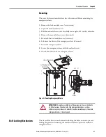
The cover of the mechanical release has to be removed before mounting the
emergency release.
1. Remove the lock module cover (seven screws)
2. Open the manual release cover
3. Pull the manual release cover forcefully at an angle of 45° until it unlatches
4. Remove the manual release cover downwards
5. Re-attach the lock module cover (six screws)
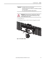
6. Lubricate the driver of the emergency release all around
7. Insert the emergency release
8. Secure the emergency release with the enclosed screw
9. Check the function of the emergency release
Figure 5 - Mounting Emergency Release
Bolt Locking Mechanism
The Access Box has two mechanisms for locking the bolt actuator to prevent
locking the guard and restarting the machine while an operator is inside the
safeguarded area.
ATTENTION:
The mechanical lifetime of the emergency release is limited to
20,000 actuations. Then the bolt of the locking module does not allow
further emergency releases. To make this function available again, the whole
locking module has to be exchanged.
!
3
2
4
A-A 1:1
45°
8
7
5
1
A
A
6
Self-tapping Screw
M2.5 x 14-T8
enclosed
Lid Seal Kit Included
Bolt
Driver

