28
Rockwell Automation Publication 440G-UM001B-EN-P - May 2016
Chapter 4
Description of Operation
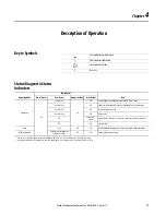
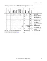
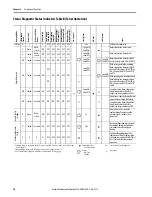
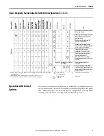
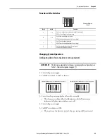
Status/Diagnostic Status Indicators Table A (Standalone Operation)
Open
Not in-
serted
OFF
OFF
OFF
OFF
OFF
OFF
Long OFF
Short ON
Normal operation, door is open
Closed
Not in-
serted
OFF
OFF
ON
OFF
OFF
OFF
Long ON,
short OFF
Normal operation, door closed
Closed In-serted OFF
OFF
ON
ON
OFF
OFF
Long ON,
Short OFF
Long ON,
Short OFF
With active guard lock monitoring:
Normal operation, door closed, bolt
inserted. Safety outputs FO1A and
FO1B are OFF.
ON
With inactive guard lock monitoring:
Normal operation, door closed, bolt
inserted. Safety outputs FO1A and
FO1B are ON.
Closed Inserted
ON
ON
ON
ON
ON
OFF
Normal operation, door closed and
locked.
Open
Not
inserted OFF
OFF
OFF
OFF
OFF
OFF
3 x
Door is open; unit is ready to
configure another handle assembly
(only 3 minutes after power-up).
Closed Inserted
ON
ON
ON
ON
ON
OFF
2 Hz
Handle configuration, tip: to prevent
the interruption of the handle
configuration, close door and switch
on guard locking.
X
X
X
OFF
OFF
OFF
OFF
OFF
Positive acknowledgement after
completion of the handle
configuration. Cycle power or apply
24V to RST for at least 3 seconds to
resume normal operation.
* Latching fault; to reset, use the RST input or briefly disconnect the device from
the power supply.
** Non-latching fault; open safety guard and close it again to reset.
***See Troubleshooting and Assistance in Appendix A on
.
Status indicator not
illuminated
status indicator illuminated
Status indicator flashes
x
Any state
Op
er
at
in
g
Mo
de
Door
Po
sit
io
n
Po
siti
on
of
the
Bo
lt
To
ng
ue
Guard
Locking
Sa
fe
ty
O
ut
pu
ts
FO1A
and
FO1B
Door
Mount
ing
Ou
tp
ut
(O
D)
B
olt
To
ngue
Monitoring
(O
T)
Gu
ard
Lo
ck
in
g
M
on
-
itor
in
g
Ou
tput
(O
L)
Diagnos
tics
Moni
-
tori
ng
O
utp
ut
(O
I)
Po
w
er
(gr
een)
Sta
te
(g
reen)
DI
A
(red
)
Loc
k (y
ello
w
)
Sta
te
Norma
l Opera
tion
Ha
ndl
e
Co
nf
ig.
St
an
db
y
Set
up


