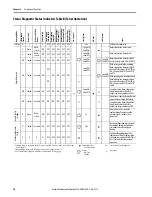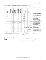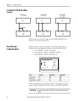
Rockwell Automation Publication 440G-UM001B-EN-P - May 2016
33
Description of Operation
Chapter 4
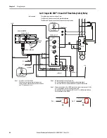
The multifunctional access box lock modules ending in –C04 (E-stop with
three push buttons) require the following rework if dual lock solenoid control
is desired:
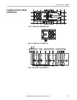
• The yellow/black wire inside the MAB needs to be moved from
terminal x2.8 (H4 – illumination of push button S4) to x3.6 (IMP2).
• Remember to remove the jumper between IMP1 and IMP2.
Proving Basic Lock Function
With Active Guard Lock Monitoring
1. Switch on operating voltage.
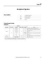
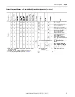
The State status indicator flashes (5 Hz) as the device performs a self-test
(up to 8 seconds). When the self-test is complete, the State status indicator
flashes at regular intervals.
2. Close all safety guards and insert the bolt tongue into the locking module.
For Power to Lock versions, activate guard locking.
• The safety outputs FO1A/FO1B are ON
• The machine must not start automatically.
• It must not be possible to open the safety guard.
• The State status indicator and the lock status indicator are illuminated
continuously.
3. To start the machine, use the control system.
• It must not be possible to open the guard door as long as the machine is
running.
4. To stop the machine and unlock the door, use the control system.
• The safety guard must remain locked until there is no longer any risk of
injury.
• It must not be possible to start the machine as long as the guard locking
is deactivated.
• It must be possible to open the safety guard.
Repeat steps two through four for each safety guard.
IMPORTANT
If illumination of push button S4 is an absolute requirement, another signal
(for example, one of the diagnostic signals OT, OI, or OL) could be given up
instead. In that case, simply move the wire for the unrequired signal to
terminal x3.6 for IMP2.

