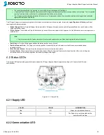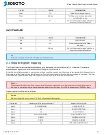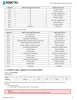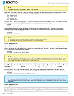
3-Finger Adaptive Robot Gripper Instruction Manual
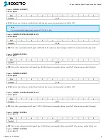
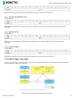
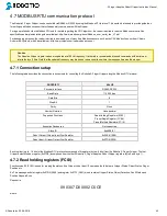
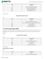
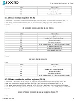
BITS
DESCRIPTION
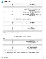
09
SlaveID
17
Function Code 23 (read and write multiple registers)
07D0
Address of the first requested register,
read
0002
Number of registers requested (2),
read
03E9
Address of the first written register
0002
Number of registers to
write
(3) to
04
Number of data bytes to follow (2 registers x 2 bytes/register = 4 bytes)
00E6
Value written to register 0x03E9
3CC8
Value written to register 0x03EA
00FF
Cyclic Redundancy Check (CRC)
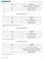
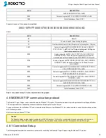
Response is:
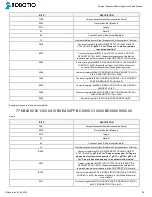
09 17 04 E0 00 00 00 47 27
where
BITS
DESCRIPTION
09
SlaveID
17
Function Code 23 (read and write multiple registers)
04
Number of data bytes to follow (2 registers x 2 bytes/register = 4 bytes)
E000
Content of register 07D0
0000
Content of register 07D1
4727
Cyclic Redundancy Check (CRC)
Caution
The 3 Finger Adaptive Gripper register values are updated at a 200Hz frequency. It is thereforerecommended to send FC23 commands with a
minimum interval delay of 5ms.
4.7.6 Modbus RTU example
This section depicts the example given in section 4.6 when programmed using the Modbus RTU protocol. The example is typical of a pick and place
application. After activating the Gripper, the robot is moved to a pick-up location to grip an object. It moves again to a second location to release the
gripped object.
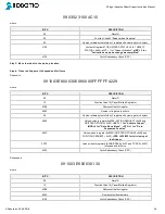
Step 1: Activation Request
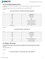
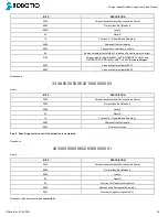
Request is:
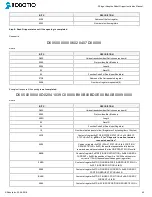
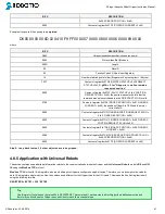
09 10 03 E8 00 03 06 01 00 00 00 00 00 72 E1
where
BITS
DESCRIPTION
09
SlaveID
10
Function Code 16 (Preset Multiple Registers)
03E8
Address of the first register
0003
Number of registers to write to
06
Number of data bytes to follow (3 registers x 2 bytes/register = 6 bytes)
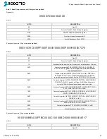
©Robotiq inc. 2008-2018
46

