20
Operating and Maintenance Instructions – 4 Design and function
Rittal Liquid Cooling Package Plus
table temperature and then routed in front of the 482.6 mm (19") level in the
server enclosure.
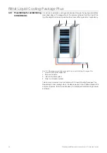
Fig. 12:
Air routing on the Liquid Cooling Package Plus (top view)
1
Fan module
2
Air inlet
3
Heat exchanger
4
Air outlet
5
2nd air inlet (optional)
6
2nd air outlet (optional)
The temperature control of the cold air which is blown in takes place through
constant comparison of the actual temperature with the setpoint temperature
set on the Liquid Cooling Package Plus' control unit (default is +20 °C).
If the setpoint temperature is exceeded, the control valve in the cooling water
system opens, and the heat exchanger is provided with cold water. The control
valve is infinitely variable (can open from 0 to 100%). In addition, the tempera-
ture differential between the cold air that is blown in and the warm air that is
drawn is used to determine and set the fan speed. The control attempts to keep
the air temperature constant in front of the 482.6 mm (19") level by activating
the control valve.
Any condensate which may develop is collected in the condensate collecting
tray that is integrated in the water module of the Liquid Cooling Package Plus.
Upon reaching a defined condensate level in the collecting tray, the level sen-
sor activates the condensate pump. The pump leads the condensate out of the
Liquid Cooling Package Plus. Further, a condensate overflow hose leads from
the tray to the exterior, so that, if necessary, (e.g. in the event of a defective level
sensor or a defective condensate pump) liquid is led away.
3
2
5
4
6
1
Note:
The water flow temperature should always be set so that the temperature ne-
ver falls below the dew point (cf. Fig. 13).

