15
Operating and Maintenance Instructions – 4 Design and function
Rittal Liquid Cooling Package Plus
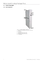
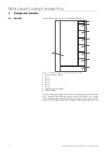
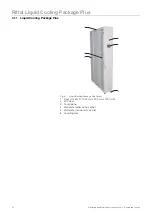
Fig. 6:
Liquid Cooling Package Plus - rear
1
Mains connection
2
Control unit (Basic CMC)
3
LCP door
4
Fan
5
Fan control unit
6
Water module control unit
7
Water module
8
Levelling foot
The Liquid Cooling Package Plus consists of a solid welded frame in which the
heat exchanger, fan modules, and the water module are installed. The frame
stands on four levelling feet, which may be used to align the unit with the bayed
server enclosure. One wide and one narrow wall plate are mounted on both the
left and right sides. A vertical divider plate is positioned at the joint of the two
plates, which separates the Liquid Cooling Package Plus into warm and cold
air sections.
The wide wall plates on the front right and left sides of the device form the cold
air section together with the divider plate and the built-in air/water heat ex-
changer. The wall plates have been punched with air outlet openings along
their entire length in the front and rear to ensure cold air supply to the server
and rejected hot air supply to the heat exchanger.
The narrower wall plates close off the rear of the device and form the warm air
section together with the divider plate. The wall plates have been punched with
air inlet openings along their entire height and width to ensure the removal of
warm air from the server.
Eight shelves are positioned between the wall plates that divide the Liquid Coo-
ling Package Plus into five installation spaces of differing heights. The control
unit (Basic CMC) sits on the top shelf. Installation spaces for the fans and con-
trol units for the six fan modules are located below. All components of the coo-
ling water supply and condensate management are integrated into the water
module on the floor of the Liquid Cooling Package Plus.
7
1
2
5
4
4
3
6
8

