Family Aqua Condens 3.5 BIS
26
ENGLISH
27
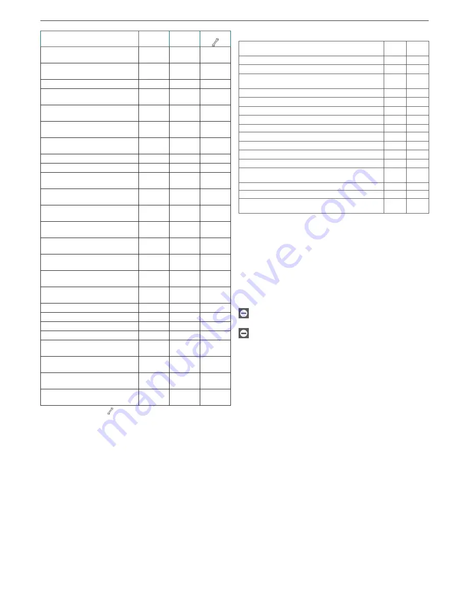
FAULT DESCRIPTION
Alarm
code
RESET
icon
Icon
RETURN-DELIVERY PROBE
DIFFERENTIAL (D)
28
YES
YES
FLUE GAS OVERTEMPERATURE
PROBE (D)
29
YES
YES
FAN (cycle start) (D)
34
YES
NO
FAN CYCLE IN PROGRESS
(high rpm) (D)
37
YES
YES
INSUFFICIENT SYSTEM
PRESSURE (D**)
40
YES
NO
INSUFFICIENT SYSTEM
PRESSURE (T**)
41
NO
YES
WATER PRESSURE
TRANSDUCER (D)
42
YES
YES
ELECTRONIC CARD (D)
50-59
YES
YES
DHW PROBE 1 (T) (°)
60
NO
YES
MINI-ACCUMULATION ALARM
(not displayed on this model)
65
YES
YES
PRIMARY PROBE SHORT
CIRCUIT/OPEN (D)
70
YES
YES
DELIVERY PROBE
OVERTEMPERATURE (T)
71
NO
NO
RETURN PROBE SHORT
CIRCUIT/OPEN (D)
72
YES
YES
SECOND HEATING SYSTEM
PROBE ABSENT
75
NO
YES
LOW TEMPERATURE
THERMOSTAT (T)
77
NO
YES
DELIVERY/RETURN
DIFFERENTIAL (T)
78
NO
YES
DELIVERY/RETURN
DIFFERENTIAL (D)
79
YES
NO
SYSTEM FAULT (D)
80
YES
YES
SYSTEM FAULT (T)
81
NO
YES
SYSTEM FAULT (D)
82
YES
YES
SYSTEM FAULT (T)
83
NO
YES
BOILER STOP SIGNAL SENT TO THE
OT DEVICES (not displayed on this model)
89
-
-
PRIMARY HEAT EXCHANGER
CLEANING (-)
91 (-)
NO
YES
CONNECTION FAILURE BETWEEN
INTERFACE AND MAIN CARD
J0
-
-
CONNECTION FAILURE WITH
THE REMOTE CONTROL PANEL
J1
-
-
The display of 43 and
indicates the activation of the automatic
venting cycle, lasting about 2 minutes. For further details, refer to
paragraph “Initial start-up”.
(D) Definitive
(T) Temporary. In this operating status, the boiler attempts to resolve
the fault situation autonomously
(°) See the NOTE on the previous page
(**) If these two errors arise, check the pressure shown on the hydrom-
eter.
If the pressure is insufficient (< 0.4 bar - red field), perform the fill
-
ing operations described in the “Filling and draining the systems”
chapter.
If the system pressure is sufficient (> 0.6 bar - light blue field), the
fault is due to a lack of circulating water. Contact the Technical
Assistance Centre.
(-) Contact the Technical Assistance Centre.
Q - Regular scheduled maintenance
OPERATIONS
1st
YEAR
2nd
YEAR
Inspection of sealing components
°
°
Cleaning of the primary heat exchanger flue gases side
°
°
Cleaning of the combustion chamber,
fan and venturi tubes
°
°
Checking of the water and gas safety devices
°
°
Checking the gas output and make any adjustments
°
°
Checking the draught and flue gases pipe
°
°
Cleaning of the burner and checking its firing
°
°
Checking the hydraulic operations
°
°
Combustion analysis
-
°
Checking and lubricating the hydraulic unit components
-
°
Checking the system seals
-
°
Washing of the heat exchanger
-
°
Checking the efficiency of the electric
and electronic components
-
°
FAN EFFICIENCY (only for vacuum chamber versions)
°
°
Checking the condensate discharge system
°
°
CHECKING THE CONDENSATE
NEUTRALISER (if installed)
°
°
NOTE: the maintenance operations described above, must be car-
ried out every two years in accordance with regulations in force
.
R - Cleaning
The only cleaning operations that we recommend are those involving
the external boiler panels, which should be cleaned using just a cloth
dampened with soap and water.
In the case of stubborn marks, dip the cloth in a mixture of 50% water
and methylated spirits, or use specific products.
Do not use fuels and/or sponges soaked in abrasive solutions
or powder detergents.
It is forbidden to carry out any cleaning operations before dis-
connecting the boiler from the mains electricity supply; to do
this, turn the main system switch to “off”.


