background image


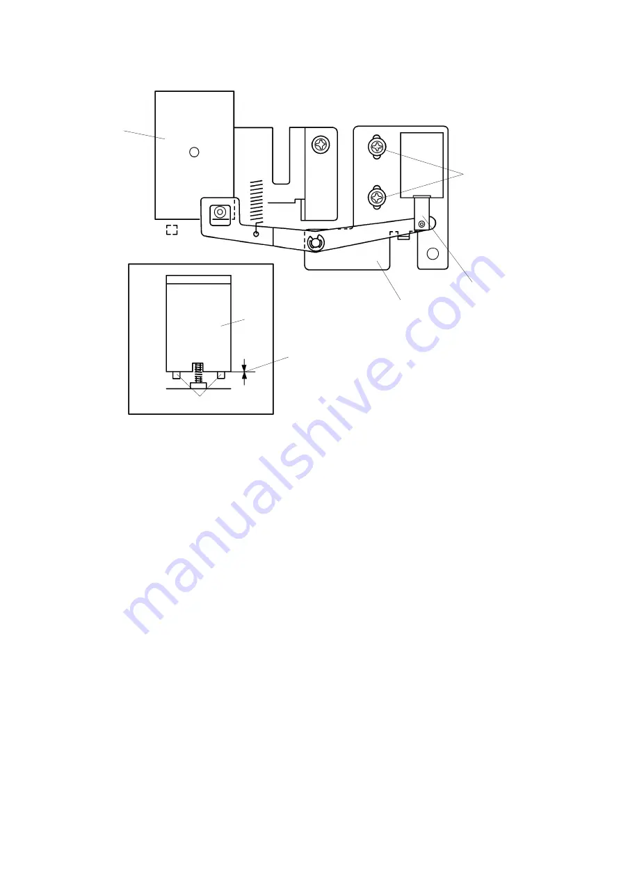
  6. Push up the plunger [F] by hand. Check the distance between the bottom

of the separation plate [H] and stoppers [G]. The distance should be
between 0 and 0.5 mm. The stoppers [G] are on the front side of the plate
[E].

  7. If the distance is more than 0.5 mm, then loosen the 2 screws [I] and

adjust the position of the bracket [J].

[Front View]

 0.5 mm

[J]

[F]

[I]

[H]

[H]

[G]

1 December 1993

5-32

Summary of Contents for VT3500

Page 1: ...SPECIFICATION 1 1 2 GUIDE TO COMPONENTS AND THEIR FUNCTION 1 4 3 OPERATION PANEL 1 8 4 PRINTING PROCESS 1 10 5 MECHANICAL COMPONENT LAYOUT 1 11 6 ELECTRICAL COMPONENT LAYOUT 1 12 7 ELECTRICAL COMPONE...

Page 2: ...RALL 2 12 2 2 ORIGINAL FEED MECHANISM 2 16 2 3 ORIGINAL FEED DRIVE MECHANISM 2 17 2 4 ORIGINAL SIZE DETECTION 2 18 2 5 ELECTRICAL TIMING 2 20 2 6 CIRCUIT 2 28 3 MASTER FEED SECTION 2 30 3 1 OVERALL 2...

Page 3: ...PAPER DETECTING AND PRINTING PRESSURE ON OFF MECHANISM 2 60 5 3 PRINTING PRESSURE ON OFF MECHANISM FOR A4 LT DRUM 2 61 5 4 PRINTING PRESSURE RELEASE MECHANISM 2 62 5 5 CIRCUIT 2 63 6 DRUM SECTION 2 6...

Page 4: ...CHARGE COUPLED DEVICE 2 92 9 2 A D CONVERSION PCB 2 94 9 2 1 Overview 2 94 9 2 2 Inversion and Amplification 2 95 9 2 3 A D Conversion 2 96 9 2 4 Reference Data Correction 2 99 9 3 IMAGE PROCESSING PC...

Page 5: ...cator 2 144 10 2 7 Master Eject Error Message 2 145 10 2 8 Paper Misfeed Message 2 145 10 2 9 Paper Delivery Error Message 2 145 10 2 10 Paper Wrap Message 1 2 146 10 2 11 Paper Wrap Message 2 2 146 1...

Page 6: ...ATION REQUIREMENTS 3 1 1 1 ENVIRONMENT 3 1 1 2 ACCESS TO THE MACHINE 3 2 1 3 POWER SOURCE 3 2 2 ACCESSORY CHECK 3 3 3 INSTALLATION PROCEDURE 3 4 3 1 MAIN BODY 3 4 3 2 PAPER CASSETTE 3 10 3 3 COLOR DRU...

Page 7: ...3 VR 4 8 1 3 4 TP 4 9 1 4 EXPECTED LIFE of PARTS 4 10 1 5 SPECIAL TOOLS 4 10 2 SERVICE PROGRAM MODE 4 11 2 1 SERVICE PROGRAM MODE OPERATION 4 11 2 1 1 Service Program Mode Access Procedure for engine...

Page 8: ...2 6 USER CODE MODE 4 27 2 6 1 User Codes 4 27 2 6 2 How To Use a User Code 4 27...

Page 9: ...1 OVER VIEW 5 9 3 2 ADJUSTING THE REDUCTION RATIO MOIRE ADJUSTMENT 5 11 3 3 ADJUSTING THE FOCUS MTF ADJUSTMENT 5 12 3 4 ADJUSTING THE READING START POSITION IN THE MAIN SCAN DIRECTION 5 13 3 5 ADJUSTI...

Page 10: ...EARANCE OF THE PAPER FEED SECTOR GEAR STOPPER 5 39 6 10 ADJUSTING THE CLEARANCE OF THE SECOND FEED ROLLER SECTOR STOPPER 5 40 6 11 ADJUSTING THE FEED LENGTH OF THE SECOND FEED ROLLER 5 41 6 12 ADJUSTI...

Page 11: ...LLER 5 64 8 10 ADJUSTING THE INK ROLLER WITH THE DRUM UNIT 5 65 8 11 ADJUSTING THE POSITION OF THE INK SUPPLY SOLENOID 5 66 8 12 ADJUSTING INK DETECTION 5 67 8 13 SCREEN 5 68 8 14 DRUM DRIVE BELT 5 69...

Page 12: ...CONTENTS 6 TROUBLESHOOTING 1 ELECTRICAL COMPONENT TROUBLE 6 1 2 TROUBLESHOOTING 6 5 2 1 IMAGE TROUBLE 6 5 2 2 PAPER FEED TROUBLE 6 9...

Page 13: ...2 CCD CIRCUIT 7 2 3 TAPE MARKER CIRCUIT OPTION 7 3 4 PAPER SIZE DETECTION CIRCUIT 7 5 5 AC DRIVE CIRCUIT 7 6 6 POWER SUPPLY CIRCUIT 7 7 7 THERMAL HEAD DRIVE CIRCUIT 7 9 8 A D CONVERTER CIRCUIT 7 11 9...

Page 14: ...8 2 2 2 DRIVE AND CUTTING MECHANISM 8 3 2 3 MANUAL CUT 8 5 3 INSTALLATION 8 6 3 1 ACCESSORY CHECK 8 6 3 2 INSTALLATION PROCEDURE 8 7 4 REPLACEMENT AND ADJUSTMENT 8 10 4 1 CUTTER REPLACEMENT 8 10 4 2 C...

Page 15: ...SECTION 1 OVERALL MACHINE INFORMATION...

Page 16: ...ed eject Leading Edge Margin 10 mm 0 39 Print Paper Size Maximum 325 mm x 447 mm 12 7 x 17 5 Minimum 90 mm x 148 mm 3 6 x 5 8 Printing Area Maximum 290 mm x 405 mm 11 4 x 15 9 at 20 C 65 RH Print Pape...

Page 17: ...eight Original Scanning Time 3 ms 1 line Original Guide Movement distance 90 mm to 310 mm 3 54 to 12 2 Original Feed Speed 21 4 mm sec while master processing 87 8 mm sec not master processing Pixel D...

Page 18: ...ry Air knife vacuum delivery Delivery Side Plate Movement distance 80 mm to 327 mm 31 5 to 12 9 Print Counter 7 digits Supplies Master Thermal master 320 mm width Master roll 225 masters 1 roll Roll d...

Page 19: ...2 GUIDETOCOMPONENTSANDTHEIRFUNCTION 1 2 3 4 5 6 7 8 9 10 11 12 13 14 15 1 December 1993 1 5...

Page 20: ...over Open when removing the master eject box 7 Main Switch Use to turn the power on or off 8 Master Eject Unit Open Button Press to remove misfed paper or a misfed master 9 Original Table Place the or...

Page 21: ...16 17 18 19 20 21 22 23 24 25 26 27 28 1 December 1993 1 7...

Page 22: ...position the originals correctly 22 Original Table Release Lever Use to open the original table unit to the left for master installation 23 Feed Roller Pressure Lever Use to adjust the contact pressur...

Page 23: ...ality of the original 6 Make Up key Press to use the make up function 7 Combine 2 Originals key Press to combine two originals onto one print image 8 Image Density key Press to make prints darker or l...

Page 24: ...backwards on the print paper 21 Memory Class Indicators Shows the number entered in memory mode or class mode 22 Number keys Press to enter the number of prints 23 Memory Class key Press to select gr...

Page 25: ...ge signal read by the CCD into digital signals and sends them to the thermal head to plot holes on the master The master then wraps dround the drum 5 Paper Feeding Sends paper separately to the drum s...

Page 26: ...Paper Table 13 Separation Plate 14 Lower Separation Roller 15 2nd Feed Roller 16 Doctor Roller 17 Press Roller 18 Ink Roller 19 Paper Exit Pawl Air Pump 20 Paper Exit Pawl 21 Transport Unit 22 Paper...

Page 27: ...6 ELECTRICAL COMPONENT LAYOUT 1 2 3 4 5 6 7 8 9 10 12 13 14 15 16 17 18 19 20 23 24 25 26 27 28 29 30 31 33 34 36 37 39 40 41 42 43 38 11 21 22 32 35 1 December 1993 1 13...

Page 28: ...r 18 Cassette Size Detection PCB 19 Paper Table Height Sensor 20 Image Processing PCB 21 Separation Plate Release Solenoid 22 Transformer 23 Paper Table Lower Limit Sensor 24 Main PCB 25 Printing Pres...

Page 29: ...Main Motor 51 Drum Rotation Sensor Pulse Generator 52 Paper Table Drive Motor 53 Paper Table Drive Motor Capacitor 54 Paper Feed Solenoid 55 AC Drive PCB 56 Master Eject Clamper Solenoid 57 Image Posi...

Page 30: ...etection Sensor 69 Master Eject Sensor 70 Master Eject Solenoid 71 Air Knife Motors 72 Master Eject Box Switch 73 Master Eject Motor 74 Thermal Head Drive PCB 75 Reverse Roller Magnetic Clutch 76 Cutt...

Page 31: ...ressure Plate Motor Raises and lowers the pressure plate 71 Air Knife Motors Rotates the fan to separate the paper leading edge from the drum 73 Master Eject Motor Sends used master into the master ej...

Page 32: ...riginal width 13 Paper End Sensor Informs the CPU if the paper is set on the paper table 14 Paper Width Sensor Informs the CPU of the paper width 19 Paper Table Height Sensor Informs the CPU if the pa...

Page 33: ...scanner unit is open 12 Paper Table Down Button Informs the CPU to turn on the paper table drive motor to lower the paper table 15 Paper Table Open Switch Checks whether the paper table is opened corr...

Page 34: ...er Switch Detects when the cutter position is far right non operation side 82 Left Cutter Switch Detects when the cutter position is far left operation side Printed Circuit Board 8 CCD PCB Converts li...

Page 35: ...Breaker Cuts the AC line off 38 Drum Rotation LED Turns to green from red when the drum stops to the home position 43 Fluorescent Lamp Applies light to the original for exposure 48 Noise Filter Filter...

Page 36: ...ve Pulley 8 Main Drive Belt 9 Transport Belt 10 Printing Pressure Pulley 11 Printing Pressure Gear 12 Idle Gear 13 Idle Pulley 14 Main Motor 15 Paper Table Drive Motor 16 Paper Feed Cam Gear 17 Master...

Page 37: ...SECTION 2 SECTIONAL DESCRIPTION...

Page 38: ...it goes through the eject rollers and into the master eject box A pressure plate then compacts the used master Drum B rotates in reverse opposite to printing direction Master eject rollers A rotate L...

Page 39: ...B and gears C and D Gear F drives the lower first eject rollers H The belts I transmit drive from the first eject rollers to the upper and lower second feed rollers J If the drum master detection sen...

Page 40: ...urns in reverse opposite to the printing direction When the A3 DLT drum is 70 from the home position the master eject solenoid A turns on and the supporter C rotates counterclockwise on the upper ejec...

Page 41: ...solenoid A turns off separating the lower first eject rollers C from the drum When the ejected master passes between the upper and lower first eject rollers the master eject sensor B is actuated The m...

Page 42: ...nergized while the drum turns another 18 degrees to try to catch the master If the master eject sensor once again fails to detect the master then the drum returns to its home position and the misfeed...

Page 43: ...F turns counterclockwise as it engages the clamper sector gear thus opening the master clamper G This releases the master from the drum The drum keeps on turning until the interrupter at the rear sid...

Page 44: ...aster eject box is compressed by the pressure plate A If the full master detection sensor K does not turn on when the pressure plate goes down it means the master eject box is filled with ejected mast...

Page 45: ...At this time the master eject motor B stops and the pressure plate is held in the upper position Pressure Plate Motor Lock Detection To prevent the pressure plate motor from locking E 12 lights up on...

Page 46: ...ainst the drum surface The master eject solenoid is de energized when the drum rotates X2 degrees more The drum rotation angles X1 and X2 depend on the drum type This machine has two types of drums on...

Page 47: ...00 milliseconds later the drum completely stops during this period the master eject clamper solenoid is de energized and the drum starts rotating forward The drum then returns to its home position The...

Page 48: ...16 Pulse signal goes to Low and the LED lights when the main switch is turned on Master Eject Solenoid E Out 103 10 Signal goes Low when the solenoid turns on Master Eject Motor F Out 103 11 Signal g...

Page 49: ...CCD Charge Coupled Device C The electrical signal from the CCD is converted into an 8 bit digital signal in the A D conversion PCB Then the upper 6 bits of the 8 bits are used in the image processing...

Page 50: ...irect light and reflected light the same A heater E is wrapped around the fluorescent lamp The lamp stays on for one minute when the main switch is turned on to quickly raise the lamp temperature This...

Page 51: ...monitors the temperature inside the machine If the temperature is low the increased resistance of TH601 drops the voltage at A and the control temperature of the heater thermistor heater ON OFF tempe...

Page 52: ...too bright To correct this a shading plate A is placed in front of the lens This blocks some of the light and distributes it more uniformly CCD Charge Coupled Device The CCD C is a solid state device...

Page 53: ...original activates the original registration sensor I The 1st original transport rollers start rotating again after the drum section completes the preparation for the master making SADF Mode The sepa...

Page 54: ...the ADF drive motor F dc motor through a series of gears G to L The pull out rollers E are driven by the ADF motor through a drive belt D The original pressure plate P is pressed down on the original...

Page 55: ...errupted the machine determines the original width as shown in the below table The original size sensors are 4 photointerrupters Original Size A3 DLT B4 LT LG A4 B5 A5 HLT Original Size Sensor 3 C o x...

Page 56: ...ds when the Master Making key is pressed If the operator ignores the indication and presses the Master Making key again the machine goes ahead with normal processing If the original size is different...

Page 57: ...Drum Position Sensor First Original Sensor Master Motor Key Main Motor Reversing Lamp On Signal ADF Drive Motor First Drum Position Sensor Original Registration Sensor Second Original Sensor Original...

Page 58: ...ng fed and the original scanning starts Since there is a 5 5 millimeter distance until the leading edge of the original reaches the scanning position the CCD reads the platen cover as a standard white...

Page 59: ...6 5 millimeters T3 When the Master making key is pressed the original is fed 8 5 millimeters before it stops From this point on the timing continues in the same manner as in the ADF mode Master Eject...

Page 60: ...y a plus The shift length is represented as L For example if the original image moves 100 millimeters backwards in the sub scanning direction this is represented as L 100 mm There are three image shif...

Page 61: ...ignal is energized when the original is fed 8 5 millimeters after the drum stops rotating The image is scanned from 3 millimeters after the leading edge of the original Then the scanned image is plott...

Page 62: ...the original is fed 8 5 millimeters after the drum stops rotating Therefore the original scanned from 3 millimeters after the leading edge of the original When L is 8 millimeters the scanned image is...

Page 63: ...bilize At the same time the original scanning signal is energized The CCD reads the platen cover as a standard white level until the leading edge of the original reaches the CCD scanning position The...

Page 64: ...10 M M CN607 8 GND 24V SOL 24V 24V CN601 b7 b5 a7 a1 a5 b1 a3 b3 a9 b9 a10 b10 a11 CN402 A7 A5 B7 B1 B5 A1 B3 A3 B9 A9 B10 A10 B11 CN404 a11 a2 a3 b31 b30 a1 a10 a4 a12 a13 a14 a15 a16 B2 B3 A31 A30...

Page 65: ...6 Signal goes Low when the sensor detects original Original Pressure Solenoid D Out 607 2 Signal goes Low when the solenoid turns on 2 lines from A D conversion PCB to main PCB increase current carry...

Page 66: ...ED SECTION 3 1 OVERALL The thermal head B burns the image scanned by the CCD on the master A as it is being fed to the drum C The master is then clamped to and wrapped around the drum A B C 1 December...

Page 67: ...60 degrees past the actuation position of the second drum position sensor C the cam H moves inside the drum and the master feed clamper solenoid D turns on When the drum turns another 58 5 degrees the...

Page 68: ...D and the lower feed roller C for master feeding When the magnetic clutch A turns on the rotation of the upper feed roller D is transmitted to the reverse roller L through the relay gears B thus feedi...

Page 69: ...y the master buckle sensor D When the sensor turns on the main motor turns on at 10 rpm to rotate the drum The main motor turns off when the sensor turns off So the master is fed by repeating the ON O...

Page 70: ...es the rotating direction so the cutter holder B starts moving toward the front Then the cutter motor A stops turning when the cutter holder B goes back to its home position and pushes the left cutter...

Page 71: ...0 degrees in reverse past the second drum position sensor actuation position T1 T3 T2 T4 T5 T6 First Drum Position Sensor Second Drum Position Sensor Main Motor Reversing Original Transport Motor Mast...

Page 72: ...starts buckling when the reverse roller magnetic clutch turns off T4 After the reverse roller magnetic clutch turns off the master is fed 5 millimeters more Then the master feed clamper solenoid is d...

Page 73: ...tops after the master is fed X1 and X2 millimeter X1 and X2 depend on the drum type as follows Drum Type A3 DLT A4 LT X1 mm 410 206 X2 mm 60 61 T5 The drum main motor stops after the master has been f...

Page 74: ...E In 104 2 Pulse signal goes to Low when the button is pressed Reverse Roller Magnetic Clutch F Out 108 14 Signal goes Low when the clutch is energized Cutter Motor Forward G Out 108 5 Signal goes Hi...

Page 75: ...per separation roller B and lower separation roller E Because of the separation system if a few sheets of paper are picked up from the paper stack paper table by the paper feed roller A only one sheet...

Page 76: ...er feed roller cam C the sector gear J turns clockwise and the gear H is turned counterclockwise The rotation of the gear H is transmitted to the upper separation roller shaft B by a one way clutch in...

Page 77: ...assembly in the direction in which the paper feed roller is pulled up When the feed pressure lever B is moved up the spring A is also moved up Thus the tension of the spring is increased weakening the...

Page 78: ...lower separation roller does not turn in the paper feeding direction It turns in the opposite direction due to the one way clutch bearings D provided on both right and left separation levers A When 2...

Page 79: ...er is fed out from the rollers the lower separation roller C and its shaft D spring back against roller A Fig 2 This rotates the lower separation roller and insures that it will wear out evenly Four p...

Page 80: ...ide pad levers to the right Normally the side pads pressure should be released by moving the levers to the left The separation plate pressure can be adjusted to match the type of paper being used The...

Page 81: ...er on the paper table moves down from the paper feed roller D and the paper feed bracket A is pulled down by its own weight At this time the shaft B pushes down the left separation lever C and this mo...

Page 82: ...and the separation plate C moves down from the upper separation roller This mechanism allows for easy removal of any paper caught between the upper separation roller and the separation plate After th...

Page 83: ...r 900 milliseconds Then The paper return motor starts rotating in reverse This helps the spring D pull back the levers In reverse the motor does not turn the levers directly through the gears because...

Page 84: ...om the sector gear as a clearance is formed between the pin of the sector gear D and the stopper When the feed roller gear turns counterclockwise its rotation is not transmitted to the lower second fe...

Page 85: ...upper roller At the beginning of each cycle the two rollers are apart they will come together halfway through the cycle and at the end of the cycle they will again be apart At first the rollers are ap...

Page 86: ...turned At this point the paper arrives from the first paper feed rollers The leading edge hits the two rollers and the paper buckles slightly This insures that the paper will go into the rollers strai...

Page 87: ...paper table stay B through a bracket A The paper table bracket C mounted under the table is fixed on both ends of the adjusting dial shaft When the adjusting dial is turned clockwise the feed table b...

Page 88: ...the light from the photocoupler which up to now was cut off by the lever and that causes the paper table motor H to turn OFF and stop raising the paper table As printing proceeds and the paper level r...

Page 89: ...E H D G F D C A B C I J K 1 December 1993 2 53...

Page 90: ...per Size Master Plotting Area Width mm Length mm A3 B4 A4 A4 S B5 B5 S A5 DLT LG LT LT S HLT 292 256 208 292 180 256 146 278 214 214 278 138 407 351 284 197 244 169 197 407 343 266 203 203 S Sideways...

Page 91: ...lective sensor on the paper detection PCB is activated the machine determines the paper size as shown in the below table Paper Size A4 S LT S B5 S LT A4 B5 A5 HLT A3 DLT B4 LG Paper Width Sensor 0 C o...

Page 92: ...he magnet position for each of size paper is described on the back of the cassette Depending on which reed switches A B C D are activated the machine determines the cassette size as shown in the table...

Page 93: ...e second drum position sensor is activated the paper table drive motor starts rotating This lifts the paper table until the height sensor is re activated approximately 30 millisecond after the motor s...

Page 94: ...e signal goes Low The table moves up Paper Table Down Relay I Out 105 12 The paper table down relay is energized when the signal goes Low The table moves down Paper Table Brake Relay J Out 105 13 Acti...

Page 95: ...A detects whether paper is fed correctly to the second paper feed roller section or not Only when the paper is correctly fed printing pressure is applied the press roller B touches the drum to transf...

Page 96: ...is being fed the paper fed presses down the paper detecting feeler E Then the paper detecting arm D turns clockwise to release the pressure ON OFF lever As a result the pressure ON OFF bearing contin...

Page 97: ...rum is used printing pressure should be released sooner because the master on the A4 LT drum is shorter than the master on the A3 DLT drum This is to prevent the press roller from getting dirty Before...

Page 98: ...des out the drum unit to remove the jammed sheet the drum surface and the press roller may be damaged To prevent this printing pressure is released from the drum if a paper misfeed is detected When a...

Page 99: ...s not interrupted the print counter signal is applied for 100 milliseconds to increase the total counter and decrease the counter on the operation panel T2 When the printing pressure sensor is not int...

Page 100: ...nk Roller D Press Roller E Paper F Drum In this section ink is supplied from the ink cartridge and is applied to the ink roller uniformly The ink is then transferred to the printing paper through the...

Page 101: ...ve mechanism uses helical gears because they turn more quietly Notice gear A the last gear of the drive and gear B at the rear end of the drum they each have a part cut out of the flange K When the dr...

Page 102: ...the drum unit in the machine Fig 1 At the same time the top of the right stopper C turns on the drum detection switch E The switch E tells the machine that the drum unit is set Fig 3 Pulling the leve...

Page 103: ...ting when the drum unit is slid out the drum stopper A drops into the drum lock B This secures the drum D When the drum unit is put back the front side plate of the main body C holds the drum stopper...

Page 104: ...stops the drum unit from being pulled out any further Now if the operator pulls handle A the drum unit won t fall out When the operator pulls stopper release D in this direction arrow he pushes up dr...

Page 105: ...n The stopper lock arm A then locks the left stopper C in place This prevents the drum unit from being removed when it isn t in the home position The Drum Rotating button D is to rotate the drum manua...

Page 106: ...etector detects less ink on the ink roller M the ink supply solenoid E turns on and the ink supply stopper F releases clutch G allowing the gear D to turn The pin C moves the pump shaft up and down as...

Page 107: ...adjusted to give a distance of 0 08 millimeters between itself and the ink roller It rotates to create an even thickness of ink The ink roller does not touch the screen F when not printing However dur...

Page 108: ...ter C Printing starts when the Print Start key is pressed When there is no master on the drum the black seal is exposed The black seal does not reflect light back to the sensor The M indicator on the...

Page 109: ...th color ink terminals no 2 and no 3 should be linked using a short connector B This will turn on the color indicator The short connector is an accessory of the unit and is included with it NOTE To us...

Page 110: ...ting pin and the ink roller C or doctor roller A ground The detection pulse is triggered by the dropping edge of the standard pulse that is input from TRIGGER 2 When ink is present electrostatic capac...

Page 111: ...0 rotations and the no ink signal remains LOW the No Ink indicator blinks When this happens and when the Reset key is pressed the drum turns 40 rotations to supply ink When the 0 key is pressed while...

Page 112: ...he voltage between TP102 and ground becomes more than 2 volts when a master is on the drum Ink Supply Solenoid E Out 104 17 Signal goes Low when the solenoid is energized Drum Lock Solenoid F Out 104...

Page 113: ...nal goes Low when the drum is installed CN118 2 and 4 are shortened The A3 or DLT Drum indicator will light when CN118 2 and 5 are open A4 LT Drum Detection H In 104 16 Signal goes Low when the A4 LT...

Page 114: ...ss Roller H Paper The exit pawl C and the air knife B separate the paper from the drum A and the vacuum fan F in the transport unit E pulls the paper against the belt D as the belt moves the paper to...

Page 115: ...l lever E then turns clockwise along the surface of the exit pawl drive cam F Therefore the exit pawl also comes near the drum until the stopper D contacts the adjusting screw C This keeps a small cle...

Page 116: ...lts The first and second paper exit sensors A and B check for paper jams The paper exit jam check is done when printing pressure is applied and the printing pressure sensor is interrupted Jam Conditio...

Page 117: ...rough idle gears a belt and a shaft The gear B rotates and drives the piston C back and forth The piston moves forward and pushes a jet of air out through the nozzle D This jet of air helps push down...

Page 118: ...delivery table This prevents the ink on freshly printed sheets from being smeared The angle of the wing guide can be changed by moving the guide release lever B Usually the wing guide release lever i...

Page 119: ...n the front side of the paper delivery table pushes down on lever C which raises arm D When arm D is in the upper position lever E cannot move forward When the delivery table is opened arm D is pulled...

Page 120: ...ghtly raised up from the 10 downward slant position spring tension pulls the lever downward and the pin engages the lever This stops the table at the level position Normally the table position should...

Page 121: ...energized Air Knife Motor E Out 103 13 Signal goes Low when the motor is energized Air Knife Motor F Out 103 14 Signal goes Low when the motor is energized Air Knife Motor G Out 103 15 Signal goes Lo...

Page 122: ...table height sensor is activated the vacuum fan motor and the air knife motor turn on T4 When the counter indicates 0 and the 2nd drum position sensor is activated the vacuum fan motor and air knife m...

Page 123: ...1 December 1993 2 87...

Page 124: ...ifted 20 mm 5 mm steps up or down on the page by pressing the forward or backward Image Position key on the operation panel This rotates the first and second paper feed roller cam to change the paper...

Page 125: ...wards the outside of the cam gear and the lever turns clockwise The lever C drives gear E clockwise through gear D and the first paper feed roller and the second paper feed roller cams F mounted on th...

Page 126: ...image position sensor The image positioning motor turns off when the image is at the selected position Nine different image position settings can be selected by pressing the Image Position key 1 2 3...

Page 127: ...1 December 1993 2 91...

Page 128: ...ODD CLOCK EVEN CLOCK SH A D Conversion PCB LSYNC SH RS OS Dummy Empty Pixels 32 Dummy Pixels 4 Data 84 Effective Pixels 5 000 3 ms 5 120 Counts One Scanning Line EVEN CLOCK ODD CLOCK SH RS OS EVEN CL...

Page 129: ...s line data stored in the capacitors are transmitted in parallel to two shift registers one for odd pixels and one for even pixels Then the odd and even pixel data are serially output An output transi...

Page 130: ...processing PCB The original background and the distortion of the light path are monitored to obtain the exact image data SHMRT VPH PKHTM PKHST 0 0 50 1 7V CCD PCB OS 8 bit 8 bit 8 bit REF _ REF VR VR...

Page 131: ...CCD output the image data is sent to IC629 pin 2 while the charged voltage in C657 is applied to IC629 pin 3 Therefore the difference in voltage between the image data and the black limit level is in...

Page 132: ...ing PCB as 8 bit digital signals The digital signal for each pixel is determined as follows 1 The CCD converts the scanned image to an analog video signal and sends it to the A D conversion PCB as an...

Page 133: ...onstant at 1 7 volts Only the high reference terminal voltage varies In the A D converter the difference in voltage between the REF voltage and the REF voltage is divided into 256 steps The analog ima...

Page 134: ...example data A 70 and B 255 are expressed in 8 bit form and sent through the eight terminals BAD 0 to BAD 7 shown in the table on the right Data Pixel A B Decimal 70 255 BAD0 0 1 BAD1 1 1 BAD2 1 1 8...

Page 135: ...ions from the image data the distorted data are applied to the reference data Thus the image data are corrected when they are converted into digital data 2 Original Background Correction The white pea...

Page 136: ...A D Converter Selector Selector A Scanning Plotting LSYNC Clock Image Processing PCB Amplification LSYNC Scanning Plotting SHMRT PKHST PKHTM 5 lines Standard White Peak Hold Original Background Peak...

Page 137: ...e platen cover have been scanned the peak hold set signal PKHST turns on to clear the standard white peak voltage VPH SW in the peak hold circuit While the 64 millimeter width 1 024 pixels in the midd...

Page 138: ...oltage and the black peak level voltage VL 1 7 volts is applied to the low reference voltage terminal REF Also during this period the platen cover white data are directly sent to the A D converter The...

Page 139: ...e voltage terminal VR of the D A converter 50 percent of the difference in voltage between the original background peak voltage and the black peak voltage is applied to the low reference voltage termi...

Page 140: ...A D converter 1 7 volts is applied to the low reference voltage terminal REF Also the image datum of each pixel sends to the A D converter directly the image datum is then digitized to an 8 bit signal...

Page 141: ...e binary processor In this step the image density is determined according to the level selected by the Image Density key Lighter Normal Darker 1 or Darker 2 The single bit image data are modified in t...

Page 142: ...the make up mode only which is selected by the Contrast key Normal Light Tone or Dark Tone Then the 8 bit image data are converted to single bit white or black data by the half tone processor There a...

Page 143: ...ce and the difference between that of the original an ideal difference is called the Modulation Transfer Function MTF If the MTF is too low edges of the image tend to be lost In this model the MTF cor...

Page 144: ...ls two steps to the left and right and 1 2 of the values of the pixels above and below are subtracted from the new value of the target pixel If the result is less than zero then the pixel datum is set...

Page 145: ...0 factory setting Setting it at 1 2 or 3 will help to better reproduce low contrast originals NOTE If SP31 is set to a higher level 2 or 3 stains scratches etc in the light path will appear on prints...

Page 146: ...or 8 pixel elements data for imaginary points by the magnification processor As a result the image is reduced to 80 140 Enlargement Data for 10 pixel elements of a main scanning line are expanded into...

Page 147: ...magnification and image shift processor simultaneously with the magnification process Data for one main scanning line are once stored in a line memory This memory has enough room to hold one main sca...

Page 148: ...is set to white if it is equal or below the threshold level See the above figure The threshold level varies according to the image density level This level is selected by the Image Density key Lighte...

Page 149: ...o be changed by changing the compensation ratio Normal Light Tone or Dark Tone The normal contrast setting is also applied for the photo mode without the make up mode The compensated image data is out...

Page 150: ...better reproduce the lighter parts of the image and the whole image will darken a bit On the other hand when Darker Tone key is selected the 8 bit output concentrates on the dark tone parts of the ima...

Page 151: ...photo mode is on and the make up mode is off CAPIX CAPIX Correlative density Assignment of adjacent pixels is used when the screen mode is not selected normal level When an image signal converted into...

Page 152: ...both half tone and solid images are well reproduced but with dithering solid images do not come out as well This is because dithering uses more graduation steps than a solid image such as a simple di...

Page 153: ...re slightly out of step with the CCD pixel elements due to some magnification error when they were scanned As a result each CCD pixel has a different value as shown in the above figure Since the lengt...

Page 154: ...t half tone graduations are introduced on prints using only black and white pixels This is done by changing the ratio of black pixels to white pixels The figures above show an example of a 4 x 4 16 pi...

Page 155: ...ingle bit data There are two kinds of dither matrices to allow for the fine and coarse screen modes A uniform gray area of an original is scanned and the pixel datum is set at 55 It then goes through...

Page 156: ...t command sheet are picked out from the corresponding memory by the area selector The image data of the original and command sheet data are combined and edited in the selection circuit When a pattern...

Page 157: ...ly one command can be selected for each command sheet up to four sheets from seven modes See the following table of modes for designated area When two or more command sheets are used select a appropri...

Page 158: ...wo or more command sheets are used at a time only one command can be selected for all command sheets from four modes See the following table of modes for outside designated area Step 4 Set the command...

Page 159: ...ea Command sheet Original closed area method Print Closed area method Diagonal line method Fn 1 Fn 11 1 Line mode Fn 2 Fn 12 2 Outline mode Fn 3 Fn 13 3 Delete mode Fn 4 Fn 14 4 Photo mode Fn 5 Fn 15...

Page 160: ...The following commands are for the area outside the designated area s MODE SAMPLE COMMAND NO Undesignated Area Command sheet Original Print Fn 1 1 Line mode Fn 2 2 Outline mode Fn 3 3 Delete mode Fn...

Page 161: ...Background Patterns The 40 background patterns shown below can be selected 1 2 3 4 5 6 7 8 9 1 December 1993 2 125...

Page 162: ...13 14 15 16 17 18 10 11 12 1 December 1993 2 126...

Page 163: ...19 20 21 22 23 24 25 26 27 1 December 1993 2 127...

Page 164: ...28 29 30 31 32 33 34 35 36 1 December 1993 2 128...

Page 165: ...37 38 39 40 1 December 1993 2 129...

Page 166: ...ows Separation the area to be designated as follows Make a space more than 2 mm Make a space more than 2 mm Designate area by a closed line Double circle pattern Only the outer circle will be recogniz...

Page 167: ...using a pencil or a color pen The line has low image density As the designating line is too light no designated area is recognized Mark using a black pen 5 Type of command sheet 1 Rough paper is used...

Page 168: ...dwriting ability the designated area the neighboring image may or may not be recognized as a designated area 1 There should be more than 2 mm clearance between the line and image 2 Mark the line away...

Page 169: ...hrough the thermal head drive PCB The power source VHD varies from one head to another since the average resistance AVR of the elements varies Therefore when the thermal head or power supply unit is r...

Page 170: ...the thermal head drive PCB through the image processing PCB The pulse signal is split into four pulse signals ENR 1 to 4 in the thermal head drive PCB Then they are separately applied to the four bloc...

Page 171: ...r each elements block CLK Clock pulse from the image processing PCB The thermal head consists of 72 sets of circuits as shown in the figure The 72 sets are divided into four blocks which are separatel...

Page 172: ...re checking circuit Then based on the datum obtained the opposite datum is sent to the thermal heating element This either heats or cools the element as required 2 The actual plotting data is sent to...

Page 173: ...y Memory 2 The line data and previous line data are compared and the pre heat and or cool data for each thermal heating element are serially sent to the thermal head as the first output The line data...

Page 174: ...d ENR signals are triggered by the rising edge of the clock pulse CLK T2 When the second output data the last half of DATA 1 for the first one block 1152 pixels data have been stored in the shift regi...

Page 175: ...rature Signal Level SC Code Thermistor 54 C 1 17 V CN109 A8 E 04 Thermistor Under 54 C Over 1 17 V Recovery Thermal Guard 85 C 0 V CN107 9 E 08 Thermal Guard Under 85 C 5 V Recovery The CPU also light...

Page 176: ...ating elements 1 Defective thermal head drive PCB or image processing PCB 2 Disconnection of the related connector Main PCB CN109 A7 image processing PCB CN404 b7 CN403 20 or thermal head drive PCB CN...

Page 177: ...to return the SP mode to its original setting after disabling the safety switch 2 The cover open indicator can be canceled by turning on the DIP switch 101 on the main PCB When this switch is turned o...

Page 178: ...cover is closed or the paper table and paper delivery table are opened 10 2 2 Key Counter Indicator Condition Guidance Display Message Key counter is not set SP mode data of address 3 is 1 SET THE KE...

Page 179: ...ode Cover open indicator is on Machine is in operation 4 The master eject box indicator turns off when the master eject box is set or the Reset key is pressed after the master eject box is removed 10...

Page 180: ...n indicator master eject box indicator key counter indicator or ink supply indicator turns on 4 When the master roll is set this indicator turns off 10 2 6 Paper Supply Indicator Condition Guidance Di...

Page 181: ...ch the paper detecting feeler The printing pressure sensor is not activated PAPER FEED JAM REMOVE JAMMED PAPER NOTE When the Reset key is pressed if the 1st and 2nd paper exit sensors are OFF jam indi...

Page 182: ...e 2nd paper exit sensor does not turn on after the 1st paper exit sensor turns on PAPER WRAP JAM REMOVE JAMMED PAPER NOTE When the Reset key is pressed if both printing pressure sensor and 1st paper e...

Page 183: ...NAL JAM REMOVE ORIGINAL The original is not fed During the master making process cover is opened or Stop key is pressed while original is being fed The ADF cover is opened when the original is set in...

Page 184: ...exceeds the print paper width when multiplied by a magnification ratio CHECK THE PAPER SIZE PRESS MASTER KEY 2 NOTE 1 When this message is displayed input from the Make up key Image Positioning key F...

Page 185: ...and READY TO START is displayed 2 If there is no master on the drum when the Print Start key is pressed M indicates and MASTER NOT WRAPPED is displayed The display message changes to READY TO START 2...

Page 186: ...ombine 2 originals mode is selected 4 In combine 2 originals mode the trailing edge of the 1st image has a 2 mm margin and the leading edge of the 2nd image has a 4 mm margin These margins vary accord...

Page 187: ...mode is selected 4 In combine 2 originals mode the trailing edge of the 1st image has a 2 mm margin and the leading edge of the 2nd image has a 4 mm margin These margins vary according to the magnific...

Page 188: ...e the center of the image does not shift Maximum Image Width 290 mm Master Plotting Width 292 mm Screen Mesh Width 297 6 mm Master Width 320 mm Master Plotting Width 292 Original Master Screen Paper A...

Page 189: ...ize The machine will not plot the last 2 mm of the original on the master Master Plotting Length LM Lo 10 2 x 100 A3 DLT LM 410 A4 LT LM 206 Magnification Ratio Original Master Original Length Lo Max...

Page 190: ...he 2nd drum position sensor if the 1st paper exit sensor is still OFF the main PCB detects a paper misfeed d When the drum has rotated 25 2 after activating the 1st drum position sensor if the 2nd pap...

Page 191: ...CN104 17 CN104 6 SOL CN103 19 CN103 22 M CN103 21 CN103 10 SOL CN103 26 CN103 5 SOL CN103 25 CN103 6 SOL PSU VMG 24V 2A FU102 5A CN107 7 Master Eject Solenoid Master Feed Clamper Solenoid Master Ejec...

Page 192: ...SECTION 3 INSTALLATION...

Page 193: ...d turn over at least 3 times an hour Avoid dusty areas 5 If the location is air conditioned or heated place the machine a where it will not be subjected to sudden temperature changes from low to high...

Page 194: ...l a 115 V 60 Hz 5 5 A b 220 V 240 V 50 Hz 2 7 A 2 Voltage must not fluctuate more than 10 3 Make sure the plug is firmly inserted in the outlet 4 Avoid multiwiring 5 Do not pitch the power cord More t...

Page 195: ...nstructing Cards 2 B Original Exit Tray 1 C Thermal Head Cleaner Set 1 C 1 Cleaner bottle 1 C 2 Replacement felt 10 C 3 Cleaner pen 1 D Master Spool 2 E Base Pad 2 Editing Sheet 1 Operating Instructio...

Page 196: ...ove 3 Open the front door and slide out the drum unit B 4 Open the master clamper and remove the clamp C 5 Open the paper delivery table and remove the strip of tape D protecting the end fence 6 Open...

Page 197: ...machine Then raise the rear side of the machine and position the other base pad B under the machine 9 Secure the machine to the table with the two screws C packed with the table NOTE Make sure the mac...

Page 198: ...10 Install the original exit tray A while bending the side edges of the original exit tray as shown A 1 December 1993 3 6...

Page 199: ...the position of the end plate D and the side plates E according to the printing paper size Refer to the paper size scale on the table 14 Install the ink cartridge F a Open the front door and lower th...

Page 200: ...e as shown in the illustration e Insert the leading edge of the master roll under the platen roller f Return the pressure release lever to the original position g Plug in the power cord and turn on th...

Page 201: ...iginal face down on the original feed table c Press the Master Making key D d Select the lowest print speed 1 with the Speed key E and press the Print Start key F Make prints at this speed until the p...

Page 202: ...on and tighten the 6 screws NOTE The paper size positions are marked on the cassette 3 Affix the proper paper size decals D to the cassette at the positions shown 4 Slide the sensor actuator E into th...

Page 203: ...ing to the following procedure 1 Open the drum case A and remove the red cushion 2 Open the master clamper B and remove the paper C protecting the drum surface 3 Stick color seals D on the ink holder...

Page 204: ...ion panel lights to indicate that the color drum unit is installed 6 Set the color ink cartridge in the ink holder 7 Press the Reset key once while holding down the 0 key to start the machine idle cyc...

Page 205: ...late with the mounting holes of the key counter holder and secure them with 2 screws F packed with the key counter holder 5 Connect connector G and reinstall the main switch cover A 6 Access the servi...

Page 206: ...SECTION 4 SERVICE TABLES...

Page 207: ...Gear Fig 1 J Second Feed Sector Gear Fig 1 F Gear of the Paper Feed Cam Shaft Fig 1 A Paper Table Slide Groove Both front side and rear side Fig 1 H Paper Table Drive Gear Fig 1 G Bearings for the Up...

Page 208: ...of the Master Pressure Plate Drive Arms Fig 5 R Paper Exit Air Pump Drive Gears Fig 6 T Inside of the Air Pump Piston Grease Mobil Ep 1 Fig 6 U ADF Bearings for the Separation Roller Shaft Grease She...

Page 209: ...Q Fig 4 R S Fig 5 T U Fig 6 V Fig 7 1 December 1993 4 3...

Page 210: ...nspection every 6 months Section Item Standard Procedure Optics Original Platen Cover Wipe off the stains using a soft cloth damped with ethyl alcohol Exposure Glass Wipe with a dry cloth Paper Feed P...

Page 211: ...ide and outside of Drum Wipe off the built up ink and paper powder using a cloth damped with ethyl alcohol Ink Holder Plotter Platen Roller Wipe off the paper powder using a cloth damped with water Ot...

Page 212: ...essive thermal head temperature 2 Thermistor short E 05 Malfunction in the image shifting section 1 Image position sensor connector disconnected 2 Defective image position sensor E 06 The drum rotatio...

Page 213: ...1 Encoder output does not change within 3 seconds of the main switch being turned on or the Clear Mode key being pressed 1 Defective image position motor 2 No power supply E 12 1 The upper or lower pr...

Page 214: ...um the LED lights LED103 2nd Paper Exit Sensor When a paper is detected the LED lights LED104 Master Eject Sensor When the master is under the master eject sensor the LED lights LED105 Ink Detection W...

Page 215: ...ter Detection Sensor Voltage ON More than 2 V OFF 0 9 V TP103 2nd Paper Exit Sensor Voltage ON More than 2 V OFF 0 9 V TP104 Master Eject Sensor Voltage ON More than 2 V OFF 0 9 V TP105 Ink Detection...

Page 216: ...prints Paper Feed Roller 6 months or 300 000 prints Upper Separation Roller 1 year or 600 000 prints Lower Separation Roller 2 000 000 prints 2nd Feed Roller Brake Belt 1 000 000 prints Separation Pla...

Page 217: ...ter the desired SP mode number listed in the service program table NOTE SP mode number can be shifted up or down by pressing the Zoom key or 4 To cancel the SP mode press the Clear Modes key 2 1 2 Ser...

Page 218: ...e value or mode set at the factory will be displayed on the LCD at the end of the second line 2 Enter the desired value or mode using the number keys listed in the service program table 3 Press Enter...

Page 219: ...ax Print Limits the maximum print quantity that can be entered 0 to 9999 9999 12 A4 A3 Mag Ratio Adjusts fixed magnification ratio A4 version From A4 to A3 LT version From 51 2 x 81 2 to 81 2 x 14 50...

Page 220: ...sts the ratio of masters to prints For accounting purposes 0 to 50 0 The set number 0 to 50 is automatically added to the key counter each time a master is used 22 Read Image 0 Not used 30 Sub Scan Ma...

Page 221: ...m 6 10 mm 7 15 mm 8 20 mm 4 46 Make Up Specifies which make up background pattern is selected when make up pattern mode is selected 1 to 40 51 to 90 101 to 140 150 to 190 0 0 No background pattern is...

Page 222: ...rial prints are made after making the master 0 to 2 sheets 1 82 Skip Feed No Selects the feed interval 1 to 5 1 1 Normal operation 2 One sheet fed every two drum rotations 5 One sheet fed every five d...

Page 223: ...al number of masters made in fixed enlargement mode 0 107 Reduction Count Displays the total number of masters made in fixed reduction mode 0 108 Zoom Count Displays the total number of masters made i...

Page 224: ...1 Yes 0 130 Input Check Mode Displays the input from sensors and switches See the input check table 131 Output Check Mode Turns on electrical components See the output check table 132 All Indicators O...

Page 225: ...ay 151 Machine No Displays the machine serial number and the installation date Input the serial number and the installation date 152 Service Tel No Input the service representative s telephone number...

Page 226: ...mage problem can be printed 2 Access SP mode 3 Input No 90 and press the Enter key NOTE The factory setting is pattern No 7 If necessary input another background pattern with the Number keys 4 Press t...

Page 227: ...put 91 and press the Enter key 3 Input 1 with the number keys and press the Enter key 4 Press the Clear Modes key to leave SP mode 5 Place the command sheet and the original on the ADF 6 Press the Mak...

Page 228: ...hen a sensor or switch that is being tested is actuated A beep will also be heard 6 Press the Enter key to return the display to the initial input check menu 7 Press the Clear Modes key to leave SP mo...

Page 229: ...SN Cassette Size 1 In 10 Cassette Size Switch 3 11 SN Cassette Size 2 In 11 Cassette Size Switch 2 12 SN Cassette Size 3 In 12 Cassette Size Switch 1 13 SN Paper Size 0 In 13 Paper Width Sensor 0 14 S...

Page 230: ...n In 32 Lower Pressure Plate Sensor 33 SW Master Eject Box In 33 Master Eject Box Switch 34 SN Full Master In 34 Full Master Detection Sensor 35 SN Printing Pressure In 35 Printing Pressure Sensor 36...

Page 231: ...SOL Paper Separation Release Out 11 Turns on the separation plate release solenoid 12 SOL Ink Supply Out 12 Turns on the ink supply solenoid 13 SOL Drum Lock Out 13 Turns on the drum lock solenoid 14...

Page 232: ...the main motor 30 rpm 28 MOTOR Main 1st Speed Out 28 Turns on the main motor 1st speed 29 MOTOR Main 2nd Speed Out 29 Turns on the main motor 2nd speed 30 MOTOR Main 3rd Speed Out 30 Turns on the main...

Page 233: ...es as follows No User Code No 1 100 2 191 3 182 4 173 5 164 6 155 7 146 8 137 9 128 10 119 11 200 12 291 13 282 14 273 15 264 16 255 17 246 18 237 19 228 20 219 2 6 2 How To Use a User Code 1 Enter th...

Page 234: ...SECTION 5 REPLACEMENT AND ADJUSTMENT...

Page 235: ...ont Cover open the front door loosen the 2 screws G remove the 2 screws H C Operation Panel open the front door slide the scanner unit to the left and remove the 4 screws D Master Eject Cover open the...

Page 236: ...truction cover J and remove 1 screw K Original Table remove the 7 screws NOTE When installing the original table make sure both original guides L are set in the same position in the grooves see illust...

Page 237: ...r of the belt A Make sure that the belt deflects 2 to 3 mm 4 If it does not loosen the mounting screws B of the original feed motor C and adjust the belt tension by sliding the original feed motor as...

Page 238: ...ndard 6 0 to 6 5 mm 1 Remove the screw securing stopper A 2 Remove the separation guide plate B 4 screws 3 Adjust the position of the original pressure solenoid C This way when the solenoid is turned...

Page 239: ...GLASS 1 Move the scanner unit to the left 2 Open the ADF unit A 3 Remove both fluorescent lamp covers 4 Remove both exposure glass leaf springs B 5 Carefully remove the exposure glass C B C B A 1 Dece...

Page 240: ...4P heater connector 4 Remove the front fluorescent lamp holder A 2 screws 5 Carefully remove the fluorescent lamp B so that it does not touch the exposure glass 6 Remove the heater C from the fluoresc...

Page 241: ...Remove the guide plate A 4 Disconnect the original registration sensor connector B 5 Remove the sensor along with the securing plate C 6 Remove the original registration sensor D from the securing pla...

Page 242: ...pin 3 Remove the E rings at both ends of the feed roller shaft B 4 Remove the original feed roller assembly C 5 Replace the original feed rollers D 1 snap ring NOTE 1 A one way clutch is installed in...

Page 243: ...fter an item in the left column adjustment item is adjusted Check Item Output of White Level Shading Scan Line Position Reading Start Position of Main Scan Focus MTF Reduction Ratio Moire Adjustment I...

Page 244: ...nd access the service program mode 4 Enter 131 with the number keys to access the output check mode 5 Enter 21 with the number keys and then press the Print Start key to turn on the fluorescent lamp N...

Page 245: ...ontaining 200 dpi on the test chart can be read 2 Press the Print Start key to turn on the fluorescent lamp 3 At the same time check if the waveform looks like the one in the illustration above 4 If i...

Page 246: ...the test chart can be read 2 Press the Print Start key to turn on the fluorescent lamp 3 Check if the waveform looks like the one you see in the illustration above 4 If it does not loosen the Allen s...

Page 247: ...nsor actuator The center line is located at the leading edge of the test chart At the same time the black line should be 16 mm away from the edge of the lower original guide plate A 3 Close the ADF un...

Page 248: ...mm away from the edge of the lower original guide plate 2 Press the Print Start key to turn on the fluorescent lamp and confirm that the waveform looks like the one in the above illustration 3 If it d...

Page 249: ...DF unit 2 Turn VR601 counterclockwise until it stops 3 Press the Print Start key and leave the fluorescent lamp on for 5 minutes to stabilize the light intensity 4 Confirm that the above white level f...

Page 250: ...of the test chart is not copied Adjustment Standard 2 0 V 0 1 V 1 Close the ADF unit 2 Press the Print Start key to turn on the fluorescent lamp and leave it on for 5 minutes 3 Adjust VR on the A D co...

Page 251: ...l head or power supply unit is replaced 1 Turn off the main switch and remove the paper exit cover plate 4 screws 2 Check the voltage on the thermal head decal The voltage varies according to the indi...

Page 252: ...Lower the paper table A 2 Remove the plotter unit cover 5 screws 3 Remove the plotter unit B 2 screws C and 4 connectors D 4 Using a tension gauge apply a 110 gram load to the center of the belt E Mak...

Page 253: ...utter holder activates the switches 1 Remove the cutter unit See Cutter section 2 After moving the cutter holder A fully to the left make sure that the left cutter switch B is turned on Make sure that...

Page 254: ...the Belt Tension section 3 Remove the platen roller A 4 Remove the cutter unit cover B 2 screws 5 Remove the thermal head guide plate C 2 screws 6 Remove the cutter unit D 2 screws 7 Remove the holder...

Page 255: ...3 Remove the thermal head cover A 2 screws 4 Disconnect the three thermal head connectors B 5 Remove the thermal head C 2 screws NOTE 1 Make sure the thermal guide plate D is positioned above the low...

Page 256: ...EAD DRIVE PCB 1 Remove the plotter unit 2 Open the bottom plate A of the plotter unit 2 screws 3 Disconnect the 5 connectors a to e 4 Remove the thermal head drive PCB B 6 screws a b c d e B A 1 Decem...

Page 257: ...rinting when the image density of the solid black area on the print stabilizes d Remove the master from the drum NOTE To prevent the thermal head from overheating do not use a large solid black origin...

Page 258: ...ouch and if the solenoid is off the rollers should not touch The solenoid will be energized by enabling output check mode number 17 3 If the rollers are not adjusted well loosen the screws C and adjus...

Page 259: ...e the right front cover and inner cover 2 Confirm that the safety switch A turns off when you open the master eject unit 3 Confirm that the distance between the safety switch and the actuator is 0 1 0...

Page 260: ...crews 2 Remove the master eject unit cover A 2 screws 3 Disconnect the 3 connectors C 4 Remove the clamper D 5 While supporting the master eject unit B slide out the shaft E NOTE Be careful not to dro...

Page 261: ...TER EJECT SENSOR 1 Remove the master eject unit 2 Remove the upper master eject unit cover 3 Remove the 2 screws A 4 Disconnect the connector C and remove the master eject sensor B A B C 1 December 19...

Page 262: ...Remove the 2 E rings B and remove the upper pulley shaft C 4 Remove the 2 E rings D and remove the roller unit from the master eject unit 5 Remove the 4 E rings F and 3 gears G 6 Remove the supporter...

Page 263: ...up when the paper table is closed Adjustment Standard 0 3 to 0 8 mm 1 Make sure that the switch A turns off when the paper table is opened and that the switch turns on when the paper table is closed...

Page 264: ...d then press the Print Start key to raise the paper table 6 After the paper table stops insert a scale into the slot at the end of the paper table Make sure that the distance between the lower stay B...

Page 265: ...he upper separation roller when the paper table lowers Adjustment Standard 0 to 0 5 mm 1 Lower the paper table 2 Remove the plotter unit 3 Remove the paper feed roller unit See Paper Feed Roller Unit...

Page 266: ...tion plate H and stoppers G The distance should be between 0 and 0 5 mm The stoppers G are on the front side of the plate E 7 If the distance is more than 0 5 mm then loosen the 2 screws I and adjust...

Page 267: ...ust the feed roller pressure follow procedure 2 next page 2 After replacing the paper feed pressure spring C follow procedure 2 to adjust the roller pressure Procedure 1 1 Loosen the screw A securing...

Page 268: ...n the lower adjusting plate notch with the center notch of the link C and tighten the screw B 6 Hook a tension gauge 500 gram range to the paper feed roller shaft E Insert a strip of paper D between t...

Page 269: ...Make sure that the distance between the lower guide plate A and lower second feed roller B is between 0 and 0 1 mm as shown 2 If it is not remove both the front and rear covers and loosen the screw C...

Page 270: ...ke sure that the clearance between the bushing B and bushing supporter C is between 0 05 and 0 1 mm as shown Also manually rotate the left and right upper second feed rollers and confirm that they exp...

Page 271: ...above illustration 1 Adjust the separation plate pressure by turning the adjusting screw D NOTE Position the minus groove on the screw head vertically or horizontally Otherwise vibrations may cause t...

Page 272: ...on the paper feed solenoid A manually Then turn the rollers counterclockwise by rotating the shaft B with a 10 mm spanner 5 Measure the length of paper fed Measure from the time the paper feed roller...

Page 273: ...kwise 3 When the sector gear B fully turns clockwise make sure that the clearance between the pin C and sector stopper D is between 0 1 and 0 3 mm 4 If it is not loosen the hexagon nut E and adjust th...

Page 274: ...0 3 mm 1 Remove the rear cover of the machine 2 Gradually turn the drum rotating shaft A counterclockwise with a 10 mm spanner 3 Turn the sector gear B counterclockwise until it stops Make sure that t...

Page 275: ...e number 19 4 Turn on the paper feed solenoid manually Then gradually turn the drum rotation shaft A with a 10 mm spanner 5 Measure the paper feed length from the time the second feed roller B starts...

Page 276: ...tment Standard 178 1 Set the Image Position indicator to the 0 position and return the drum to the home position by turning off and on the main switch 2 Remove the rear cover of the machine 3 Set a pr...

Page 277: ...haft 5 Measure the degrees turned when the second feed roller sector gear C starts returning counterclockwise The second feed rollers start rotating This should be 178 6 If it is not loosen the 2 bolt...

Page 278: ...6 13 PAPER FEED ROLLER 1 Remove the left clamper A 2 Remove the left bushing B 3 Remove the paper feed roller shaft C 4 Remove the 2 paper feed rollers D B A C D 1 December 1993 5 44...

Page 279: ...ER FEED ROLLER UNIT 1 Remove the plotter unit 2 Remove 2 hexagon screws A 3 Remove the clamper B 4 Remove the paper feed roller unit from the machine by sliding the shaft to the rear B A 1 December 19...

Page 280: ...of the upper separation roller 3 Slide the shaft B in the direction of the arrow 4 Remove the guide disks C and remove the upper separation roller D NOTE When reassembling the paper feed roller unit...

Page 281: ...emove the front plate See Adjusting the Separation Plate Release Solenoid section 2 Remove the paper return motor A using a small plus screwdriver 3 Remove the spring B then remove the separation plat...

Page 282: ...into the machine 3 Remove the upper and lower guide plates E 2 screws NOTE When reassembling the guide plates make sure that the guide plates do not touch the lower second feed roller 4 Remove the spr...

Page 283: ...ation shaft counterclockwise to position the bearing of the pressure release arm B on the top of the pressure cam A 3 Make sure that the clearance between the paper detecting arm C and the pressure re...

Page 284: ...10 mm spanner turn the drum rotation shaft counterclockwise and position the bearing of the pressure release arm A on top of the pressure cam B 3 While the arm is on top of the cam make sure that the...

Page 285: ...a 10 mm spanner turn the drum rotation shaft counterclockwise and position the bearing A of the pressure ON OFF lever B on top of the pressure cam C 3 Loosen the bolt D fixing the arm E 4 Adjust the...

Page 286: ...e the rear cover of the machine 5 Set a protractor D on the image shifting shaft A Align the origin of the protractor with the edge of the solenoid bracket E 6 Using a 10 mm spanner turn the drum rota...

Page 287: ...ose To apply the proper printing pressure to the press roller Adjustment Standard 4 mm 1 Remove the rear cover of the machine 2 Adjust the clearance A to be 4 mm by turning the adjusting bolt B B A St...

Page 288: ...rm this adjustment after adjusting the clearance of the paper detecting arm 1 Manually press in the plunger of the printing pressure solenoid A At this time rotate the drum rotation shaft with a 10 mm...

Page 289: ...7 PRESS ROLLER 1 Remove the screw A 2 Slide the holding plate B to the front side of the machine 3 Remove the press roller 4 Remove both right and left bearings C 2 E rings C A C B 1 December 1993 5 5...

Page 290: ...Remove the rear cover of the machine 2 Apply a 1000 gram load using a tension gauge to the center of the main drive belt A Make sure that the belt deflects 1 5 mm 3 If it does not remove the drum unit...

Page 291: ...on button until the drum reaches the home position 3 Remove the right front cover Then confirm that the voltage between TP102 E and TP107 B on the main PCB is between 0 9 and 1 0 V 4 If the voltage is...

Page 292: ...0 1 10 rotations minute at the maximum printing speed 1 Press the Speed Change key to set the speed at the maximum level 2 Make prints After the first print the machine should produce 120 prints every...

Page 293: ...t Standard 1 mm or less 1 Remove the drum unit from the machine 2 Make sure that the distance between the center of the drum lock A and the center of the drum stopper B is less than 1 mm 3 If it is mo...

Page 294: ...screws 3 Make sure that the distance between the lock lever B and the stopper C is between 0 3 and 0 8 mm 4 If the distance is not correct loosen the two screws D and adjust the position of the soleno...

Page 295: ...ove the drum unit and open the master eject unit 2 Turn on the master feed clamper solenoid A Use Output Check mode number 15 3 Confirm that the distance E between the bushing D and the edge of the op...

Page 296: ...hen it is de energized 1 Remove the drum unit and open the master eject unit 2 Turn on the master eject clamper solenoid A Use Output Check mode number 16 3 Confirm that the distance E between the bus...

Page 297: ...metal screen from the drum unit 3 Remove the ink distributer 2 screws 4 Wipe off the ink around the ink roller A and the doctor roller B 5 Make sure that the distance between the end of the ink detec...

Page 298: ...ound the ink roller and the doctor roller 6 Insert a 0 08 mm gap gauge between the doctor roller and the ink roller Then make sure that a 0 1 mm gauge can not penetrate the gap NOTE Check the gap at t...

Page 299: ...2 Remove the tetron screen and the metal screen from the drum unit 3 Loosen the bolts A and B that secure the ink roller unit to the drum shaft 4 Insert the drum gauge C P N C2009001 in the holes in...

Page 300: ...5 1 mm 1 Remove the drum unit from the machine 2 Remove the upper ink supply solenoid cover and remove the front cover of the drum unit 3 Press in the solenoid plunger by hand and make sure that the...

Page 301: ...e 5 microsecond range 4 Turn on the main switch and install a drum with no ink Or instead remove the ink bottle and make prints until the Add Ink indicator lights 5 Make sure that the waveform is as s...

Page 302: ...en B NOTE 1 Make sure that the black seal D is on the front side outside of the screen when reinstalling it 2 Make sure that the front stay A comes under the clamper plate E when reinstalling it 3 Mak...

Page 303: ...tch off and on 2 Turn off the main switch and unplug the power supply cord 3 Remove the drum unit 4 Remove the rear cover 5 Remove the center support plate A 5 screws 6 Remove the lower support plate...

Page 304: ...y B 10 Remove two belt tension bearings C 11 Remove the pressure cam drive gear D 2 hexagon bolts E and 1 E ring NOTE Four hexagon bolts secure the gear D Do not loosen the two deeply recessed bolts F...

Page 305: ...essure cam are in proper position as explained above If the relation between the printing pressure cam G position and the drum drive gear C position is wrong printing pressure will be applied too late...

Page 306: ...it firmly in place While still holding it make sure that the hole J in the second feed cam is aligned with the upper support plate I If it is not repeat steps 7 to 10 11 Make prints to check the regi...

Page 307: ...0 8 to 0 9 V 1 Remove the right front cover of the machine 2 Wrap a sheet of 65 g m2 paper A around the drum 3 Measure the voltage between TP101 E and TP107 GND D It should be between 0 8 and 0 9 volt...

Page 308: ...exit misfeed occurs Adjustment Standard VR103 is set at the ON OFF threshold of LED103 D 1 Remove the right front cover of the machine 2 Place a sheet of 65 g m2 paper A 15 mm away from the second pa...

Page 309: ...umber 19 3 To feed a sheet of paper turn on the paper feed solenoid by hand and using a 10 mm spanner gradually rotate the drum rotation shaft and at the same time manually turn on the printing pressu...

Page 310: ...in of the protractor at the bracket of the master feed clamper solenoid 4 Manually press in the plunger of the printing pressure solenoid Release the paper detecting arm manually by rotating the drum...

Page 311: ...ston position is at the upper dead point 1 Open the front door and remove the inner cover 2 Press and hold down the Drum Rotate button until the drum reaches the home position 3 Confirm that the 13 mm...

Page 312: ...remove the inner cover 2 Remove the exit side plate A 4 screws 3 Remove the harness clamp and disconnect the two connectors B 4 Remove the two screws C 5 Take off the belt D from the pulley and remov...

Page 313: ...the E rings A and bushings B Then slide out the rollers C 3 Remove the two screws D securing the transport guide plate E 4 Remove the screw securing the harness clamp F and then remove the transport...

Page 314: ...ND PAPER EXIT SENSORS 1 Remove the transport unit See Transport Unit section 2 Turn the transport unit over 3 Remove the transport vacuum fan motor A 4 Remove the first and second paper exit sensors B...

Page 315: ...nserted into the hole of the gear B move the gear B to enable the gauge to be inserted into the hole as follows a Disconnect the image positioning motor connector C b Loosen the Allen screw D so that...

Page 316: ...ep on pressing the Image Position key if the im age position sensor is broken or removed The plastic gears between the worm gear F and gear D may break if the pin which moves along the spiral track of...

Page 317: ...SECTION 6 TROUBLESHOOTING...

Page 318: ...al Sensor ON condition Not interrupted An original is not fed in ADF mode When the Master Making key is pressed indicator A blinks OFF condition Interrupted Jam indicators A and blink after the last s...

Page 319: ...FF condition Not activated Though there is paper on the paper table paper end indicator blinks Printing Pressure Sensor ON condition Interrupted Drum rotates continuously does not stop after a trial p...

Page 320: ...ed 2 The drum starts rotating and it cannot be stopped when the Master Making key is pressed Second Drum Position Sensor OFF condition Not interrupted 1 When the Print key is pressed the drum continue...

Page 321: ...aper is set on the paper table OFF Not activated LT lengthwise paper is detected even though A5 sideways paper is set on the paper table Paper Length Sensor G ON Activated A3 paper is detected even th...

Page 322: ...ng time Has the ink inside the drum separated Ink was in storage for a long time Insufficient printing pressure applied to drum Sheet of paper wrapped under the master or two masters wrapped around th...

Page 323: ...ern mode and check the image Does the same problem still occur with the test pattern Yes No Yes No Thermal head thermal head drive PCB or image processing PCB is defective A D conversion PCB CCD PCB o...

Page 324: ...or gears in the original feed section loose Is the print image smaller than the original in the paper feed direction Is the master feed motor functioning normally Are the drive belts in the master fee...

Page 325: ...Are any of the pulleys and or gears in the master feed section loose Tighten the screws securing the pulleys and or the gears Yes 1 December 1993 6 8...

Page 326: ...ger of the paper feed solenoid been pulled out Is there enough clearance between the paper feed sector gear stopper and the stopper pin Is the paper feed solenoid energized Is the paper feed sector ge...

Page 327: ...aper feed roller shaft slipping Paper is often not fed forward at high printing speeds Lightly sand the roller shaft surface with fine sandpaper increases the coefficient of friction and replace the c...

Page 328: ...high printing speeds Is the paper detecting pin moving normally Is any paper stuck between the guide plates Are the guide plates at the correct height Check the clearance between the second feed sect...

Page 329: ...correct Is the printing pressure timing correct Is the paper detecting pin moving normally Is the upper second feed roller moving normally The upper second feed roller should move up when the pressur...

Page 330: ...the paper feed roller shaft slipping Is there enough clearance between the paper detecting arm and the pressure release arm Is the printing pressure cam timing correct Otherwise the maximum printing a...

Reviews: