background image


PRINTER CONTROLLER SERVICE MODE 

SM 5-3 

G081/G092 

Service 

Tables 

5.2  PRINTER CONTROLLER SERVICE MODE 

NOTE: 

In the Function/[Setting] column: 

• 

The related pop-up screen name and function name (if any) appear in 
parenthesis following the function description. 

• 

Comments are in 

italics

• 

The setting range is enclosed in brackets, with the default setting written 
in 

bold

• 

An asterisk (*) after the mode number means that this mode’s value is 
stored in the NVRAM. If you do a RAM reset, all these SP modes will be 
returned to their factory settings. 

• 

DFU

 stands for 

D

esign/

F

actory 

U

se only. Values marked 

DFU

 should 

not be changed. 

• 

FA

 stands for 

F

actory 

A

djustment only. Values marked 

FA

 should not be 

changed. 

• 

The Printer Controller is referred to as the Main Control Board. 


5.2.1 SERVICE MENU-CONTROLLER SERVICE MODES  

(“1. SERVICE”) 

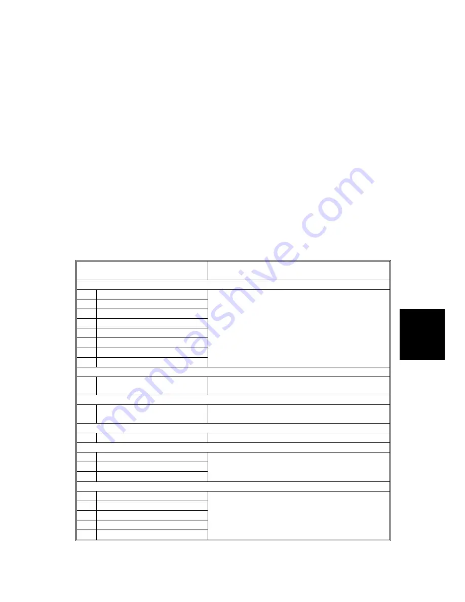
Mode No. 

(Class 1 and 2) 

Function / [Setting] 

[Bit Switch] 

– SP1001


Bit Switch 1 

Bit Switch 2 

Bit Switch 3 

Bit Switch 4 

Bit Switch 5 

Bit Switch 6 

Bit Switch 7 

Bit Switch 8 

(See “Bit Switch Settings”.) 
 

[Clear Setting]

 – SP1003


1 Clear 

Setting 

Initializes the settings in the “System” menu of the 
user tools. 

[Print Summary] 

– SP1004


1 Print 

Summary 

Prints the service summary sheet (a summary of all 
the controller settings). 

[DispVersion]

 Display Version – SP1005 

Disp Version 

Displays the version of the controller firmware. 

[ToneCtlSet]

 Toner Control Setting – SP1101 

1 Tone 

(Factory) 

2 Tone 

(Prev.) 

3 Tone 

(Current) 

Recalls the gamma settings. Select the factory, 
previous, or current setting. 

[ToneCtlSet]

 Toner Control Setting – SP1102 

*1200 x 1200 Photo 

600 x 600 Text 

1200 x 600 Text 

600 x 600 Photo 

1200 x 600 Photo 

Selects the printing mode (resolution) for the printer 
gamma adjustment. When selecting a print mode, 
an asterisk (*) is displayed in the front of the mode. 

Rev. 10/2003 

Summary of Contents for G081

Page 1: ...G081 G092 SERVICE MANUAL 001481MIU RICOH GROUP COMPANIES...

Page 2: ......

Page 3: ...G081 G092 SERVICE MANUAL RICOH GROUP COMPANIES...

Page 4: ......

Page 5: ...G081 G092 SERVICE MANUAL 001481MIU...

Page 6: ......

Page 7: ...RMISSION OF RICOH CORPORATION All product names domain names or product illustrations including desktop images used in this document are trademarks registered trademarks or the property of their respe...

Page 8: ......

Page 9: ...tion Users of this manual should be either service trained or certified by successfully completing a Ricoh Technical Training Program Untrained and uncertified users utilizing information contained in...

Page 10: ......

Page 11: ...LEGEND PRODUCT CODE COMPANY GESTETNER LANIER RICOH SAVIN G081 C7116 LP020c CL3000 CLP1620 G092 DOCUMENTATION HISTORY REV NO DATE COMMENTS 2 2003 Original Printing...

Page 12: ......

Page 13: ...ING THE PRINTER TO A COMPUTER 1 16 Connecting the printer to a computer using a network interface cable 1 16 Connecting the printer to a computer using a parallel cable 1 17 1 2 9 CONFIGURING THE PRIN...

Page 14: ...PAPER EXIT SUB ASSEMBLY 3 22 3 8 PAPER FEED UNIT 3 22 3 8 2 PAPER FEED UNIT DISASSEMBLY 3 24 3 9 IH INDUCTIVE HEATER UNIT 3 27 3 10 ELECTRICAL COMPONENTS 3 28 3 10 1 POWER SUPPLY UNIT 3 28 3 10 2 POWE...

Page 15: ...REGULAR STREAKS 4 14 4 3 13 GHOSTING 4 14 4 3 14 UNFUSED OR PARTIALLY FUSED PRINTS 4 14 4 3 15 IMAGE SKEW 4 14 4 3 16 BACKGROUND STAIN 4 15 4 3 17 NO PRINTING ON PAPER EDGE 4 15 4 3 18 IMAGE NOT CENTE...

Page 16: ...NOSTIC 5 32 Overview 5 32 Detailed self diagnostics 5 33 5 5 2 ENGINE SELF DIAGNOSTIC 5 33 5 6 USER PROGRAM MODE 5 34 5 7 DIP SWITCHES 5 35 Controller Board 5 35 DETAILED DESCRIPTIONS 6 DETAILED SECTI...

Page 17: ...ing envelopes 6 36 Paper feed speed 6 36 6 3 11 STANDARD TRAY LOCK MECHANISM 6 37 6 3 12 PAPER EXIT AND PAPER SWITCHBACK 6 38 Normal Printing Mode Not Duplex Printing Mode 6 38 Duplex Printing Mode Pa...

Page 18: ...58 6 7 5 REMARKS 6 59 Related SP Mode 6 59 6 8 IEEE802 11B WIRELESS LAN 6 60 6 8 1 SPECIFICATIONS 6 60 6 8 2 BLOCK DIAGRAM 6 61 6 8 3 TRANSMISSION MODE 6 62 Ad Hoc Mode 6 62 Infrastructure Mode 6 62...

Page 19: ...6 74 CN24 Mono Color Changer Solenoid 6 74 CN25 TB Unit Cam Switching Solenoid 6 74 CN26 Switchback Solenoid 6 74 CN27 on ECB CN1501 on Color Registration Sensor 6 75 CN28 Paper Size Detector 6 75 CN2...

Page 20: ...7 1 1 GENERAL SPECIFICATIONS 7 1 1 1 SUPPORTED PAPER SIZES 7 3 2 SOFTWARE ACCESSORIES 7 4 2 1 PRINTER DRIVERS 7 4 2 2 UTILITY SOFTWARE 7 4 3 MACHINE CONFIGURATION 7 5 PAPER FEED UNIT TYPE 3000 G342 S...

Page 21: ...ting Be careful to avoid touching those components with your bare hands HEALTH SAFETY CONDITIONS Toner including monocomponent toner and developer are non toxic but if you get either of them in your e...

Page 22: ...optical housing unit can only be repaired in a factory or at a location with the requisite equipment The laser subsystem is replaceable in the field by a qualified Customer Engineer The laser chassis...

Page 23: ...tions in this Manual This manual uses several symbols Symbol What it means Refer to section number See Core Tech Manual for details Screw Connector Lengthwise SEF Short Edge Feed Sideways LEF Long Edg...

Page 24: ......

Page 25: ...CEMENT AND ADJUSTMENT TROUBLESHOOTING SERVICE TABLES DETAILED DESCRIPTIONS SPECIFICATIONS PAPER FEED UNIT TYPE 3000 G342 TAB POSITION 2 TAB POSITION 1 TAB POSITION 3 TAB POSITION 4 TAB POSITION 6 TAB...

Page 26: ......

Page 27: ...INSTALLATION...

Page 28: ......

Page 29: ...1 Areas directly exposed to cool air from an air conditioner 2 Areas directly exposed to heat from a heater 6 Do not place the machine in an area where it will be exposed to any corrosive gas i e amm...

Page 30: ...1 G092 1 2 SM 1 1 3 MACHINE SPACE REQUIREMENT Place the machine near the power source providing clearance as shown A left side Over 10 cm 4 B rear Over 10 cm 4 C right side Over 55 cm 22 D front Over...

Page 31: ...220 V to 240 V 50 Hz 60 Hz More than 6 A 2 Permissible voltage fluctuation 10 3 Do not set anything on the power cord 1 2 MACHINE INSTALLATION 1 2 1 INSTALLING THE PHOTOCONDUCTOR UNIT WASTE TONER BOTT...

Page 32: ...om of the photoconductor unit at this time NOTE After taking the new photoconductor unit out of the bag immediately install it Do not expose it to ambient light for prolonged periods NOTE Before proce...

Page 33: ...the next step Do not touch the surface of the OPC drum s with your hands 7 Slide the front of the photoconductor carefully in Slide the unit on the cover and then push the unit in until it stops NOTE...

Page 34: ...s Maintenance Guide page 32 for added details 14 Close the right cover B of the printer slowly The Waste Toner Bottle will automatically be pushed upwards into its proper position NOTE You may wish to...

Page 35: ...in the toner s shipping bag If a large amount of toner is present inside the bag check to ensure that the cartridge s shutter is properly closed NOTE Do not open the shutter B on the bottom of the ton...

Page 36: ...not set properly you cannot close the upper cover of the printer 1 2 3 LOADING PAPER CAUTION When pulling the paper tray out be careful not to pull it strongly Doing so may cause the tray to fall caus...

Page 37: ...not exceed the limit mark B inside the tray 2 To avoid paper misfeeds the front and side guides should be set exactly to the paper size 3 Do not load different kinds of paper in the tray 6 Slide the p...

Page 38: ...avoid damaging the cord and causing a fire or an electric shock NOTE 1 Be sure to firmly connect the power plug to the socket outlet 2 The printer must be off when you plug in or unplug the power cor...

Page 39: ...nish Spanish Finnish Portuguese Czech Polish or Hungarian 2 If you use the English panel display it is not necessary to do the following procedure 1 Turn on the printer NOTE After the machine warms up...

Page 40: ...fault 5 Press the or key to display the language you want to select 6 Press the Enter key to select An asterisk will be displayed next to the selected language 7 Press the On Line key or Menu key Read...

Page 41: ...by printing the test page 1 Turn on the printer NOTE After the machine warms up Ready appears on the panel display 2 Press the Menu key 3 Press the or key to display List Test Print 4 Press the Enter...

Page 42: ...ference on the Configuration page Refer to the Firmware Update Procedure located in Section 5 of this manual Update the firmware if necessary After completing the firmware update return to this sectio...

Page 43: ...he printouts and decreasing the value lightens the printouts 2 Pressing the or key increases or decreases the value by one 8 Print another image density test sheet and check if the colors on the test...

Page 44: ...he network interface cable B to the Ethernet port on the back of the printer 3 Connect the other end of the cable to the network for example to a hub 4 Turn on the printer 5 Check the LEDs on the Ethe...

Page 45: ...t on the computer 4 To avoid electrical interference use a shielded cable 5 Do not use a parallel cable longer than 2 5 meters 8 2 feet 1 Confirm that the printer s power switch A is off 2 Turn the co...

Page 46: ...below shows an example to specify TCP IP as the active protocol 1 Press the Menu key Menu appears on the panel display 2 Press the or key to display Host Interface and then press the Enter key The int...

Page 47: ...E 1 When the Enter key is pressed the cursor moves to the next field 2 When the or key is kept pressed for a few seconds the value changes by 10 3 If DHCP is assigned the IP address can not be changed...

Page 48: ...seconds the display returns to the Network Setup setting screen NOTE shows the current setting Depending upon the firmware this setting may be located under Network Boot 7 When all of the settings ar...

Page 49: ...k OK The following languages are available Cestina Czech Dansk Danish Deutsch German English English Espanol Spanish Francais French Italiano Italian Magyar Hungarian Nederlands Dutch Norsk Norwegian...

Page 50: ...e arrives Meter charge mode disabled The Counter menu is not displayed The total counter starts from 0 Off Counting method SP5 045 1 Specifies whether the counting method used in meter charge mode is...

Page 51: ...e options Paper Feed Unit Type 3000 Unit G342 AD440 Duplex Unit G343 Printer Hard Disk Type 3000 G345 IEEE802 11b Interface Unit Type A Wireless LAN G628 IEEE1394 Interface Unit Type 4510 G336 Bluetoo...

Page 52: ......

Page 53: ...PREVENTIVE MAINTENANCE...

Page 54: ......

Page 55: ...K Fusing Unit 100K NOTE The transfer roller is supplied with the fusing unit Chart A4 LT 5 Mode Three pages per print job Environment Normal temperature and humidity Yield may change depending on circ...

Page 56: ...ter Separation pad C C Clean with water NOTE Cleaning the inside of the machine is recommended when replacing the PCUs and transfer belt unit 2 2 2 RECOMMENDED CLEANING PROCEDURE 1 Turn off the main s...

Page 57: ...REPLACEMENT AND ADJUSTMENT...

Page 58: ......

Page 59: ...ual uses the following symbols See or Refer to Screws Connector 3 1 SPECIAL TOOLS AND LUBRICANTS 3 1 1 TOOLS Part Number Description Described Section Q ty N8036701 PCMCIA Flash Memory Card 4MB 5 4 1...

Page 60: ...hen replacing parts use only the manufacturer s specified components 3 After servicing be sure to restore the insulators shields etc Open the front door A Fusing unit connector B Release the two fusin...

Page 61: ...e two screws are the green thumb screws located at either side of the transfer unit B When removing the transfer belt unit take care not to damage the transfer belt 3 4 EXTERIOR COVERS 3 4 1 FRONT DOO...

Page 62: ...to remove the front door to replace the transfer roller Avoid touching the transfer roller s surface with your hands E Transfer roller right bushing F Transfer roller left bushing G Transfer roller s...

Page 63: ...to assist unclipping the hooks Be careful not to damage the hooks or the cover C Cassette cover D Harness cover NOTE Use a penlight or other suitable light source to view how each cover hook is clipp...

Page 64: ...oks B x 2 C Top cover 7 hooks D NOTE Use caution not to damage the paper exit sensor E This cover is a very precise fit Use extra caution and work alternately from the right and left sides of the top...

Page 65: ...p cover 3 4 4 A Engine board shield cover x 8 B Engine control board All x 7 NOTE After replacing the ECB remove the EEPROM from the old board and install it on the new board If the EEPROM on the old...

Page 66: ...G081 G092 3 8 SM 3 5 2 SUB FUSING FAN AND SUB FUSING FAN DUCT Rear covers 3 4 4 Left cover 3 4 5 Top cover 3 4 4 A Sub fusing fan x 2 x 1 B Jam detection sensor board x 1 C Sub fusing fan duct x 2 x 2...

Page 67: ...lder assembly A Toner cartridge drive unit x 2 x 1 B PC guide x 1 C Toner cartridge holder assembly x 2 x 1 D Lubricating Lubricate the following parts Grease G501 when replacing them values in parent...

Page 68: ...nector is at CN22 on the engine board B Paper pickup motor bracket x 4 C Paper pickup drive gear D Grounding plate x 1 Lubricating Lubricate the following parts Grease G501 when replacing them values...

Page 69: ...lder 3 5 2 Engine control board engine board small bracket engine board large bracket 3 5 1 Toner cartridge drive unit 3 5 4 Paper pickup drive motor bracket 3 5 5 A Inner cover x 2 x 2 B Fusing unit...

Page 70: ...rts Grease 501 when replacing them values in parentheses indicate the amount of lubricant The shaft of the feed idle gear C 0 05 cc The shaft of the cam gear D 0 05 cc The shafts of the left PC idle g...

Page 71: ...e PCU gear 3 Install gears 1 3 in order of gears 1 2 and 3 4 Make sure that each alignment mark A is aligned with the mark B CAUTION Replace all PCU gears at the same time with the gears provided in t...

Page 72: ...when replacing them values in parentheses indicate the amount of lubricant The shaft of the CMY home lever A 0 05 cc The shafts of the PCU gears E 0 05 cc The inside of the bushing G 0 1 cc x 4 The i...

Page 73: ...The shafts of the CMY change gears B 0 05 cc The inner cogs 0 1 cc and outer cogs 0 1 cc on the BK change gear C The shaft of the BK change gear C 0 05 cc The shaft of the hopper change gear D 0 05 c...

Page 74: ...pulley gear flange H Feed belt I BK solenoid x 2 J BK clutch spring K BK clutch arm Lubricating Lubricate the following parts Grease 501 when replacing them values in parentheses indicate the amount o...

Page 75: ...s unit x 2 x 2 NOTE The connectors are at CN2 and CN3 on the high voltage board 3 10 6 3 5 8 POWER SUPPLY FAN MOTOR AND PSU FAN MOTOR DUCT Fusing unit 3 2 Engine control board 3 5 1 Toner cartridge ho...

Page 76: ...eye injury 3 6 1 CAUTION DECAL LOCATIONS The caution decal is located as shown below WARNING Be sure to turn off the main switch and disconnect the power plug from the power outlet before beginning an...

Page 77: ...er the plate the other wires go over the plate Be sure to re install using the exact same screws as removed B Laser scanning unit x 3 x 3 NOTE 1 To avoid dust do not disassemble the laser scanning uni...

Page 78: ...e gear F Outer gear x 2 G Inner gear x 4 H Coupling gear x 2 CAUTION The rotation switching gear I differs from the other gear J in the direction of the gear teeth see Figure 1 Lubricating Lubricate t...

Page 79: ...rts Grease 501 when replacing them values in parentheses indicate the amount of lubricant The right and left ends of the paper exit roller A 0 1 cc x 2 excluding the gear on the left end B Paper exit...

Page 80: ...ront door 3 4 1 Right cover 3 4 3 Rear cover 3 4 4 Left cover 3 4 5 A Registration clutch x 1 B Registration roller coupling gear x 1 NOTE The connector is at CN20 on the engine board 3 5 NOTE When re...

Page 81: ...ng Lubricate the following parts Grease 501 when replacing them values in parentheses indicate the amount of lubricant A The cogs on the inner gear 0 1 cc x 2 B The shafts on the outer gear 0 05 cc x...

Page 82: ...Inner gear 1 hook C Inner gears D Outer gear E Gear F Plastic washer G Ratchet arm H Feed gear I Idle gear J Screw K Gear bracket L Pickup solenoid M Bushing N Bushing NOTE Unlatch the bushing hook fr...

Page 83: ...e groove in the pickup roller shaft B Pickup roller shaft with the two pins C D Spring x 2 E Registration roller F Registration pinch roller G Paper empty registration sensor board H Registration sens...

Page 84: ...stration paper guide assembly from the support tabs remove it from the paper feed unit frame C Two bushings D Paper feed roller E Paper feed unit frame F Registration paper guide G Paper guide spring...

Page 85: ...A B The thermostat can be easily broken Fusing unit 3 2 All covers 3 4 C Interlock switch cover x 3 D IH cable shield cover x 1 E Cover x 1 F x 2 pink white black G IH harness cover x 1 H IH unit x 1...

Page 86: ...0 1 POWER SUPPLY UNIT All covers 3 4 IH unit 3 9 A Cover x 1 NOTE Slide out the cover in the arrow direction B Power supply unit x 11 x 4 NOTE Move the power supply unit in the arrow direction and sli...

Page 87: ...ICAL COMPONENTS SM 3 29 G081 G092 Replacement Adjustment 3 10 2 POWER SUPPLY UNIT DISASSEMBLY A Power supply shield cover x 10 B Power supply board x 2 x 6 C IH power supply board x 1 x 5 G081R943 WMF...

Page 88: ...re beginning the following procedures make sure you have the printer s original SMC report factory settings available EEPROM on the ECB 1 Enter SP mode and print out the SMC reports with SP5 990 if po...

Page 89: ...de data changes as indicated on the printer s original SMC report and the current SMC report printed in Step 1 of this procedure EEPROM on the ECB and the NVRAM on the Controller 1 Enter SP mode and p...

Page 90: ...S All covers 3 4 Power supply unit 3 10 1 Engine control board 3 5 1 A Laser scanning unit grounding plate x 4 B Main control board shield cover assembly x 7 C Main board shield cover x 7 D Main board...

Page 91: ...10 5 Main drive unit 3 5 6 A HV earth plate x 1 B High voltage unit with high voltage board x 6 x 4 C High voltage board shield cover x 4 D High voltage board E Spring F Color registration sensor boar...

Page 92: ...2 Rear cover 3 4 4 Left cover 3 4 5 Top cover 3 4 4 Open the right cover A Transfer belt tension unit x 2 x 3 NOTE The cables are wired through the opening of the frame and connected to the 3 connecto...

Page 93: ...AND CAM RATCHET SOLENOID A Changer solenoid B Changer lever C Changer lever spring D Transfer cam home position sensor E Cam solenoid spring F Cam ratchet with the washer G Cam ratchet solenoid H Spr...

Page 94: ...05 cc x 4 the inside edge 0 05 cc and outside edge 0 05 cc of the planetary gear base B The inside of the double teeth gear 0 05 cc C The shaft on the cam ratchet bracket 0 05 cc D The outside of the...

Page 95: ...Y PCU as follows 1 Remove the left cover 3 4 5 2 Remove the board cover A x 2 3 Push the free run button B and hold it down One or more sheet of the test pattern is output NOTE The number of sheets de...

Page 96: ...6 Open the front cover and make sure the PCU holder is correctly installed 7 Loosen the screws C NOTE You may wish to only loosen one set of screws at a time This way you can adjust the skew of eithe...

Page 97: ...1 x 1 3 14 SENSORS 3 14 1 FRONT AND RIGHT COVER OPEN DETECTION SWITCHES Front door 3 4 1 Rear cover 3 4 4 Right cover 3 4 3 Top cover 3 4 4 A Interlock switch cover x 3 B Front door open detection se...

Page 98: ...Paper pickup motor bracket x 1 B Bypass tray sensor cover x 2 C Bypass tray home position sensor board x 1 D Bypass tray paper detection sensor board x 1 3 14 3 WASTE TONER CARTRIDGE FULL SENSOR Open...

Page 99: ...e B Pickup roller unit NOTE Unlatch the pickup roller hook C and slide the pickup roller unit from the pickup roller shaft B D Gear cover with the sub tray protector E and protector spring F x 2 G Rol...

Page 100: ...D PAPER CASSETTE G081 G092 3 42 SM A Cassette gear bracket B Paper exit sensor lever C Left cam 1 hook D Cam shaft E Bushing F Upper cassette paper guide x 1 2 hooks E G081R980 WMF G081R962 WMF C G D...

Page 101: ...SSETTE SM 3 43 G081 G092 Replacement Adjustment A Holder spring B Bypass tray paper holder C Friction pad D Left paper guide E Right paper guide F Tray cover G Paper tray H Paper tray base G081R965 WM...

Page 102: ...the hook B and move it as shown by the arrows C Cassette base plate NOTE Raise the cassette base plate in the arrow direction and slide it in the arrow direction D Two springs E Pinion gear with 2 rac...

Page 103: ...TROUBLESHOOTING...

Page 104: ......

Page 105: ...L CONDITIONS 4 1 1 SUMMARY 1 All SCs are logged 2 If the problem is related to an electrical circuit board first disconnect then reconnect the connectors before replacing the PCBs 3 If the problem is...

Page 106: ...ection between high voltage supply and engine control board Defective high voltage board 1 Replace the PCU 2 Replace the transfer belt unit 3 Replace the bias terminal unit 4 Connect the cable correct...

Page 107: ...ce the engine board 3 Replace the drive unit Solenoid error 487 Any of the following solenoids has caused a short circuit changer solenoid paper feed solenoid toner supply solenoid Solenoid drive tran...

Page 108: ...board 6 Connect the cable between the engine board and fusing unit correctly 7 Replace the thermistor 8 Connect the cable between fusing unit and thermistor correctly 9 Replace the engine control boa...

Page 109: ...622 After the system starts the communication with the paper tray is unexpectedly interrupted Defective cable connection 1 Connect the cable to the paper tray correctly EEPROM error 680 Data is not wr...

Page 110: ...the engine board 2 Replace the engine board if the error is frequent 3 Replace the controller board if the error is frequent Engine start up error 670 The ready signal from the engine board is not det...

Page 111: ...diagnostic Defective controller Replace the controller Self diagnostic error Font ROM 836 The data in the font ROM on board is damaged Defective font ROM 1 Turn the main switch off and on 2 Replace th...

Page 112: ...HDD 1 Check the HDD connection 2 Reformat the HDD 3 Replace the HDD HDD Reboot error 861 The HDD does not become ready within 30 seconds after the power is supplied to the HDD Loose connection Defect...

Page 113: ...and ROM DIMM are properly connected 3 Reinstall the controller system firmware 4 Replace the controller Software update error 999 Software updating failed Controller DIP SW1 setting incorrect Defecti...

Page 114: ...oner cartridge drive unit Defective toner cartridge agitator Replace the toner cartridge Incorrect action of transfer roller Check the guide and the transfer roller Defective high voltage supply board...

Page 115: ...r Y is missing Defective engine control board Replace the engine control board 4 3 4 LIGHT PRINT Symptom Possible cause Necessary actions Loose connection between transfer roller and high voltage supp...

Page 116: ...gistration roller At intervals of 69 1 mm 2 721 inches Defective transfer roller Replace the transfer roller At intervals of 75 4 mm 2 968 inches Defective OPC drum Replace the PCU At intervals of 75...

Page 117: ...sfer roller Some parts of images are missing Defective fusing unit Replace the fusing unit 4 3 9 DIRTY BACKGROUND Symptom Possible cause Necessary actions Backgrounds are too dense Of one CMYK color D...

Page 118: ...can result in ghosting issues 4 3 14 UNFUSED OR PARTIALLY FUSED PRINTS Symptom Possible cause Necessary actions Nonstandard paper in use Use recommended paper Incorrect media type mode Select an appr...

Page 119: ...R EDGE Symptom Possible cause Necessary actions Defective PCU Replace the PCU Defective toner cartridge Replace the toner cartridge Defective transfer belt unit Replace the transfer belt unit Images a...

Page 120: ...ack PC Home Position Sensor KZPH H CN13 3 OPC Cam Home Position Sensor Board on Main Drive Unit 11 Accumulator Cam Home Position Sensor ITHOME1 H CN14 2 Accumulator Tension Unit 12 Fusing Unit Detecti...

Page 121: ...Chassis front 34 ADU Detection Sensor ADUNON H CN39 2 35 ADU Jam Detection Sensor NADUJAM L CN39 5 Inner Cover at Front side of Chassis 36 Paper Jam Sensor ACFJAM H CN3201 2 37 Paper Empty Sensor ACFP...

Page 122: ...V 4 A 250 V No response F3 4 A 125 V 4 A 250 V No response F4 4 A 125 V 4 A 250 V No response F5 4 A 125 V 4 A 250 V No response F6 4 A 125 V 4 A 250 V No response F7 4 A 125 V 4 A 250 V No response H...

Page 123: ...SERVICE TABLES...

Page 124: ......

Page 125: ...ty cannot be guaranteed any more Entering the Service Mode There are two ways to enter the service mode Method 1 Turn the machine on while pressing the On Line key and Escape key together until SYSTEM...

Page 126: ...cape then the Menu key in sequence not together These certain SP modes are generally related to the various communication options For Example SP5 851 1 Bluetooth and SP5 844 1 USB can be accessed usin...

Page 127: ...RVICE MODES 1 SERVICE Mode No Class 1 and 2 Function Setting Bit Switch SP1001 1 Bit Switch 1 2 Bit Switch 2 3 Bit Switch 3 4 Bit Switch 4 5 Bit Switch 5 6 Bit Switch 6 7 Bit Switch 7 8 Bit Switch 8 S...

Page 128: ...8 1 step 9 Black Cyan Magenta Yellow 9 0 to 255 144 1 step 10 Black Cyan Magenta Yellow 10 0 to 255 160 1 step 11 Black Cyan Magenta Yellow 11 0 to 255 176 1 step 12 Black Cyan Magenta Yellow 12 0 to...

Page 129: ...Enter key The current value appears in the column 7 Press the up arrow key or down arrow key to change the value 8 Press the Enter key The changed value is stored 9 Press the escape key 3 times 10 Se...

Page 130: ...nly Bit Function Default 0 Background areas of simple graphics RPDL R16 R55 R98 0 Not painted 1 Painted DFU 0 1 Unknown 2 byte characters R98 0 Cleared 1 Not cleared DFU 0 2 Specifies portrait landsca...

Page 131: ...gradation scales on the printout smooth from the lowest to the highest density Adjust the CMY gradation scale at the top of the chart by balancing the density of the C M and Y gradation scales the CMY...

Page 132: ...ToneCtlSet Tone Factory Adjustment Procedure 1 Enter the controller service mode 2 Use the down arrow key to select ToneCtlSet there are two of these in the menu select the second one SP1102 and press...

Page 133: ...color adjustment sheet 2 For the color you are adjusting look at the gradation scale entitled Default 3 Go along the scale until you reach the density that you wish to adjust 4 Read off the value on t...

Page 134: ...set key when the machine is off line to use the new settings NOTE The new settings will not be saved in the controller NVRAM unless you reset the controller Entering SP1101 ToneCtlSet allows you to se...

Page 135: ...e to side registration by changing the laser main scan start position for each mode 0 30 15 2 pixel step Paper Buckle Paper Buckle Process Speed Tray 1 100 Tray1 2 100 Bypass 3 100 Tray2 4 100 Tray3 5...

Page 136: ...Label 12 PostCard Doc 105 13 PostCard Adr Adjusts the fusing belt temperature for the printing ready condition The fusing temperature is depended on the paper type Ready temperature Fusing temperature...

Page 137: ...et the toner is supplied to the development unit when the main power switch is turned off and on or the machine recovers from the energy saver mode After the toner has been supplied to the development...

Page 138: ...PRINTER ENGINE SERVICE MODE G081 G092 5 14 SM 2 Mode No Class 1 2 and 3 Function Setting 33 Other 2 100 34 Other 2 124 35 Other 2 50 310 36 Envelop 2 B...

Page 139: ...splay 024 1 mm inch display Display units mm or inch for custom paper sizes 0 mm Europe Asia 1 inch USA Counter Method 045 1 Counter Method Switches the counter display The setting can only be changed...

Page 140: ...H Image Memory Handler Clears IMH data DFU 0 0 0 0 step 5 MCS Memory Control Service Clears MCS data DFU 0 0 0 0 step MCS is for network settings 8 PRT Clears the user tool settings 0 0 0 0 step 801 1...

Page 141: ...the Host Interface menu 828 72 Current I F Displays the current interface setting Ethernet or wireless LAN HDD Init HDD Initialization 832 1 HDD Init Initializes the hard disk 0 0 0 0 step Use this SP...

Page 142: ...speed mode 2 Vendor ID Displays the vendor ID DFU 3 Product ID Displays the product ID DFU 844 4 Dev Release Num Displays the development release version number DFU Bluetooth 851 1 Mode Select the Bl...

Page 143: ...it items The meter charge counter is not shown when the Menu key is pressed The PM counter resets automatically after the user replaces the fusing unit 930 2 MenteStyle Maintenance Style Year Contract...

Page 144: ...anual Use to make a line position adjustment Eng Err Stat Engine Error Status 994 1 7 00000000 0 Display the engine error status Bit 7 The fuse did not blow after installing a new PCU K Bit 6 The fuse...

Page 145: ...28 Others Displays the counter values for each paper size 0 9999999 0 0 sheet step Feed Counter 1 Tray 1 2 Tray 2 3 Tray 3 204 5 By pass Displays the number of sheets fed from each paper feed station...

Page 146: ...ted 0 99999999 0 1 page 3 PC K Page 4 PC YMC Page Display the number of pages that is calculated from drum rotation 0 99999999 0 1 page 5 Toner K Pixel 6 Toner C Pixel 7 Toner M Pixel 8 Toner Y Pixel...

Page 147: ...6 Average C 7 Average M 833 8 Average Y Displays accumulated average value of pixel coverage ratio for each color 0 100 00 0 01 step Total Memory 836 1 Total Memory Displays the capacity of memory on...

Page 148: ...etting 160 MSIS 161 MSIS OPTION 204 Printer 910 210 MIB Firmware Ver Firmware Version display 1 Controller 2 Engine 18 NIB 131 Bluetooth 150 RPCS 151 PS 152 RPDL 153 R98 154 R16 156 R55 158 PCL 159 PC...

Page 149: ...home position Home position Tray 2 Paper Paper End Sensor Tray 2 6 Paper End Sensor Paper detected Paper end Tray 2 Jam Jam Sensor Tray 2 7 0 Jam Sensor Paper detected No paper Paper Tray 2 Cassette S...

Page 150: ...r Switch Open Closed Toner Door Top Cover Switch 26 0 Top Cover Switch Open Closed Mis regist 1 Color Registration Sensor 1 27 0 10 Color Registration Sensor 1 Data range 0 to 1024 Unit 3 3 1024V Mis...

Page 151: ...ickup motor ON with the process speed of 50 mm s 7 By pass Pickup Motor OFF Turns the by pass pickup motor OFF 8 Pickup Solenoid Tray2 Turns the paper pickup solenoid for paper tray 2 ON for 1 second...

Page 152: ...22 BK Motor 100mm s Turns the BK motor ON with the process speed of 100 mm s 23 BK Motor 124mm s Turns the BK motor ON with the process speed of 124 mm s 24 BK Motor 50mm s Turns the BK motor ON with...

Page 153: ...inter s Configuration Page prior to updating the firmware Then when the firmware has been successfully updated print a second Configuration Page and confirm the results 5 4 2 ERROR RECOVERY Engine Fir...

Page 154: ...d B 5 Open the front cover or right cover 6 Turn the main switch on 7 Wait until Engine ROM is displayed NOTE 1 If you did not insert the correct PCMCIA memory card the correct message is not displaye...

Page 155: ...itch on 7 Wait until the message Onboard Sys 1 2 is displayed NOTE 1 If you did not insert the correct PCMCIA memory card the proper message is not displayed In this case press the up arrow key Exit i...

Page 156: ...2 13 Repeat steps 6 through 11 When the main switch is turned on step 6 Onboard Sys 2 2 is displayed step 7 14 Remove the PCMCIA memory card and insert the PCMCIA card that contains Network Support 15...

Page 157: ...k Standard RAM Conection Check Optional RAM Connection Check Clock Generator Check Standard NVRAM Check Font Header Check Optional NVRAM Check Real Time Clock Check Network Check Engine I F Check Inte...

Page 158: ...port for the detected errors The errors detected during self diagnostics can be checked with SP7 832 001 Diag Result Refer to section 4 2 Controller Error for details about the error codes 5 5 2 ENGIN...

Page 159: ...nergy Saver 1 Menu List Energy Saver 2 Color Demo Page Unit of Measure PS Config Page Resolution PCL Config Page B W Detect List Test Print Hex Dump System Spool Printing 2 Color Regist I O Buffer Ima...

Page 160: ...ard DIP SW No OFF ON 1 Boot up from machine Boot up from PCMCIA memory card 2 to 4 Factory Use Only Keep these switches OFF If a download attempt failed you must boot the machine from the PCMCIA memor...

Page 161: ...DETAILED DESCRIPTIONS...

Page 162: ......

Page 163: ...Printer control box Main Control Board E Power supply unit F Y toner cartridge G M toner cartridge H C toner cartridge I BK toner cartridge J Fusing unit K Paper feed unit L Paper feed motor M Power s...

Page 164: ...o the paper tray B of the main unit The duplex unit is installed on the inside of the front cover When fed from the paper trays including the bypass tray paper is sent to the transfer roller F fusing...

Page 165: ...TION The CMY motor drives the following CMY PCUs The BK motor drives the following Black PCU All four toner cartridges Transfer belt unit Transfer belt tension unit Paper feed standard cassette Fusing...

Page 166: ...to the following units Rotation to the black PCU is controlled by the BK solenoid A When the BK solenoid is turned on the BK clutch arm B unlatches from the gear in the switching gear unit H and BK mo...

Page 167: ...C Magenta PCU drive gear D Cyan PCU drive gear The CMY motor drives the following gears G081D901 WMF 8 9 7 10 2 3 5 4 Magenta PCU for OPC rotation Magenta PCU for development Yellow PCU for OPC rotati...

Page 168: ...etooth wireless interface can be installed If any of these are installed the USB2 0 board must be removed The main control board controller connects to the ECB through the video interface bus ECB Clut...

Page 169: ...e allow computers to connect to the printer using IEEE1284 parallel printer port and USB 4 Optional interface boards IEEE1394 IEEE802 11b Bluetooth These allow computers to connect to the printer usin...

Page 170: ...1 OVERVIEW A Polygon mirror B Charge roller Y M C K C OPC drum Y M C K D Transfer belt E Paper tray main unit F Paper tray optional unit G Paper tray optional unit H By pass tray I Transfer roller J...

Page 171: ...transferred to areas that were exposed to the laser beam Belt transfer A transfer belt D rotates past the drums and the toner on the drum is transferred to this belt in the order Y M C K All four colo...

Page 172: ...C K The charge rollers A contact the OPC drum B surfaces The charge on the roller is about 1100 V depending on the ambient temperature and selected print resolution This applies a uniform negative cha...

Page 173: ...s the beams are parallel and directs them to the polygon mirror C The toroidal correction lens F corrects the vertical registration errors of the beams Mirrors direct the beams to the primary lenses a...

Page 174: ...drums B The charge on exposed areas of the drum falls to about 50 V Unexposed areas of the drum remain charged at approximately 600 V Laser output power is either 0 25 mW or 0 4 mW depending on whethe...

Page 175: ...are different This prevents users from installing the cartridges in the wrong positions Toner supply When the toner cartridge has been installed in the holder a gate shutter on the bottom of the tone...

Page 176: ...the toner cartridge holder During monochrome printing a ratchet mechanism E linked to the solenoid holds the gear F which is linked to the toner supply paddle shafts of the C A M B and Y C PCUs preven...

Page 177: ...empty When the toner cartridge is not in the holder the message Reset Toner Xxxxxx is displayed where Xxxxxx indicates the color If two toner cartridges are not in the holders the message Reset Toner...

Page 178: ...the toner cartridge when the cartridge is out of toner and momentarily interrupts the LED light path After the receptor has detected this pulsing light the machine starts to count pixels When 0 26 bil...

Page 179: ...p The toner supply roller is charged to 300 volts The development roller rotates at 1 33 times the speed of the OPC drum F to ensure a sufficient supply of toner Both the toner supply roller G and the...

Page 180: ...sfer belt The spiral paddle shaft E carries the removed toner to the waste toner bottle 6 New PCU detection The K PCU has a fuse as does the YMC PCU When electricity flows through the fuse for the fir...

Page 181: ...e cam solenoid G turns on the pawl F holds the ratchet mechanism D and the solenoid turns off This action enables the shaft M to start revolving When the shaft has made a quarter revolution the pawl r...

Page 182: ...s to the 180 degree position for all pages except the final one Cam 1 B on the previous page causes the cam slider H on the previous page to slide to the right This action lifts the belt transfer roll...

Page 183: ...printing the changer solenoid J on page 6 19 stays off so the belt transfer roller changer K on page 6 19 does not slide forward Only the belt transfer roller below the black OPC belt is lifted and t...

Page 184: ...transfer belt contacts all OPC drums O Yellow magenta and cyan OPC drums 0 1 cycle 90 270 180 0 Phase Transfer belt tension Belt transfer roller K Belt transfer roller Y M C Transfer roller Waste tone...

Page 185: ...supply roller H Toner The transfer belt F contacts the OPC drums D and moves at the same speed as the drum s rotation Under the transfer belt at the contact point with each OPC drum there is a belt tr...

Page 186: ...roller E Paper feed is timed so that the leading edge of the toner image on the belt is aligned to 4 mm from the leading edge of the paper The paper advances at the same speed as the transfer belt NOT...

Page 187: ...sfer roller The belt cleaning unit B consists of the cleaning blade D and spiral shaft C The cleaning blade removes residual toner from the transfer belt E to prevent ghosting on the next print The re...

Page 188: ...addle shaft D transports removed toner waste toner to the waste toner bottle H The waste bottle has five openings one for the transfer belt cleaning unit 6 3 6 the others for the PCUs B C The waste to...

Page 189: ...level is high E the light path is blocked and Waste Toner is Almost Full is displayed After this when 4 58 billion pixels have been printed Replace Waste Toner is displayed In this case the machine co...

Page 190: ...tains the heat roller C The IH coil B heats the heat roller The heat roller heats the fusing belt D which is responsible for melting the toner on the paper Additionally the paper is pressed between th...

Page 191: ...Q SET CLR NFSRJA ROTAT E FSRNO N TH1HIG NCSAD NZCROS S IHON IHONGAT E VIN 100V Vref 2 27V Vref 0 60V AN0 AN1 Engine Control Board TH1HIG H ROTAT E TH2HIG FSRFUS E GND NFSRJA NCSAD IHON DZCRO S VIN100...

Page 192: ...Refer to illustration on pg 6 29 Pin No In Out Signal Name CN15 CN1601 CN15 CN1601 Remarks NFSRJAM 6 2 In Out Detects paper jams in the fusing unit CN15 On engine control board CN1601 On fusing unit...

Page 193: ...TH1HIGH is used to control the fusing temperature Fusing temperature control The table lists the pin locations Refer to illustration on pg 6 29 Pin No In Out Signal Name CN15 CN1601 CN15 CN1601 Remark...

Page 194: ...ontrol Slow Down Timing Chart IHPOWER IHON IHON NZCROSS Vin Threshold Vin 20 msed 50 Hz 16 7 msec 60 Hz Temperature Resistance G081D917 WMF Signal on Signal off Signal on Signal off The timing chart f...

Page 195: ...n pg 6 29 Pin No In Out Signal Name CN32 CN2503 CN32 CN2503 Remarks IHPOWER 7 3 Closes the 24V circuit IHON 6 4 Out In Provides the IH unit with electricity CN32 On engine control board CN2503 On powe...

Page 196: ...Standard tray main unit J Pickup roller optional unit K Paper tray optional unit L Pickup roller optional unit M Paper tray optional unit N Paper feed roller optional unit O Paper feed roller optiona...

Page 197: ...witch H Detects the tray and the paper size By pass paper end sensor R Detects whether there is paper in the tray NOTE The paper tray detection switch is mechanically linked to the paper size detectio...

Page 198: ...hree paper feed speeds for feed from registration roller to fusing unit depending on the selected resolution Mode Resolution dpi Feed speed mm s Print speed ppm 300 x 300 600 x 600 1 200 x 600 124 20...

Page 199: ...tandard tray and the front door E are locked when the by pass tray cover F is open There is an actuator D located on the left inside part of the by pass tray cover As the actuator releases the mechani...

Page 200: ...ives the paper exit roller gear The arrows indicate the rotation direction of the gears Sensors The paper actuates the paper exit sensor when it reaches the paper exit roller If the paper does not act...

Page 201: ...t roller B The switching lever shifts the paper path switching guide A to the right This feeds the paper between the paper exit roller and the switchback pinch roller C The paper is sent to the exit t...

Page 202: ...any of the following four different types of adjustments is automatically conducted Main scan start position control This adjustment is done when the main scan start positions of the four colors are n...

Page 203: ...ments The segments are arranged into one zigzag line that is parallel with the other lines If this adjustment adversely effects the output images deactivate SP5 995 1 5 3 1 NOTE Strictly speaking the...

Page 204: ...board 4 SDRAM DIMM 2 slots 64 MB SDRAM resident expandable up to 384 MB with a 64 MB 128 MB or 256 MB SDRAM 5 Flash ROM 8 MB flash ROM programmed for the system and network applications 4 MB mask ROM...

Page 205: ...uetooth Interface section 15 HDD option A 3 5 HDD 20 5 GB can be connected using the IDE interface The hard disk is partitioned as shown below The partition sizes cannot be adjusted Partition Size Fun...

Page 206: ...M 6 4 2 BOARD LAYOUT Flash ROM Flash ROM ASIC COMIC CPU ASIC KLAVIER IDE I F HDD ROM DIMM I F x2 SD RAM DIMM I F x2 DIP SW NVRAM I F Network I F PCI Option I F Mask ROM Engine I F LE D IEEE 1284 I F P...

Page 207: ...ing RPCS Driver Controller Host ICM Engine ICM profile Printer Engine CMYK 8 bit CMYK 8 bit K UCR BG RGB CMYK 1 bit RGB G081D937 WMFF PCL Driver Decode Scale 8 bit Color Matching Dithering ROP BG UCR...

Page 208: ...th K or CMYK toner depending on the driver settings BG UCR Black Generation Under Color Removal The RGB data is converted to CMYK data with BG UCR During CMYK conversion some CMY data is replaced with...

Page 209: ...ler SP mode Toner Limit Default 190 for text 260 for photo Adjustable range 100 to 400 Dither Processing and ROP RIP Dither patterns have been prepared for photo and text independently Dithering conve...

Page 210: ...s those jobs using locked print and collation 6 5 2 LOCKED PRINT This feature requires installing the optional HDD When using this feature the print job is stored in the machine but will not be printe...

Page 211: ...r The Tray Priority setting can be specified using the Paper Input menu of the user tools Tray Lock If Tray Lock is enabled for a tray the controller skips the locked tray in the tray search process N...

Page 212: ...bled Auto Tray Select When there is no paper tray that matches the paper size and type specified by the driver the machine searches for any tray that has paper and prints from the first tray it finds...

Page 213: ...ges with color data appear the transfer belt lifts against all drums If the pages following a color print page are black and white pages the transfer belts position changes to contact to the K drum on...

Page 214: ...line indicator stays on With energy saver 2 you can set how many minutes the printer waits before switching to energy saver mode 5 15 30 45 60 In energy saver 2 the default is on 60 minutes 15 5 sec 2...

Page 215: ...rd contains the following features which are supported in most devices Hot swapping cables can be connected and disconnected while the computer and other devices are switched on Peer to peer networkin...

Page 216: ...6 6 4 PIN ASSIGNMENT Pin No Signal Description 1 Cable Power 2 GND 3 Receive strobe 4 Transmit data 5 Receive data 6 Transmit strobe IEEE1394 Board 1394 I F 1394 I F PHY TSB41AB2 Clock Oscillator Link...

Page 217: ...6 TROUBLESHOOTING NOTES If there are problems printing using the IEEE1394 interface check the following Is the computer using Windows 2000 with Service Pack 1 minimum Has the interface card been repla...

Page 218: ...IP address is known as SCSI printing NOTE 1 Windows XP is the only OS which supports IP over 1394 Windows 9X ME 2000 Windows NT4 can also be used when used in combination with SmartNet Monitor 2 Wind...

Page 219: ...essary USB 1 1 contains the following features Plug Play Hot swapping cables can be connected and disconnected while the computer and other devices are switched on No terminator or device ID required...

Page 220: ...downstream connection to the USB device Type A connector Type B connector 6 7 4 PIN ASSIGNMENT The controller has a type B receptacle CN10 Pin No Signal Description Wiring Assignment 1 Power Red 2 Da...

Page 221: ...where the print job was cancelled When the controller board is replaced the host computer will recognize the machine as a different device Related SP Mode USB Settings are located in the printer engi...

Page 222: ...ng or moving wires Most wireless LANs can be integrated into existing wired networks Once installed the network treats wireless nodes like any other physically wired network component Flexibility and...

Page 223: ...dicators LED DESCRIPTION ON OFF LED1 Green Link status Link success Link failure LED2 Orange Power distribution Power on Power off Controller Board Engine Control Board C N1 Parallel I F Interface Boa...

Page 224: ...e in ad hoc mode and program the necessary settings This is required even if the machine will be used in infrastructure mode To switch between ad hoc and infrastructure modes use the following user to...

Page 225: ...ices Some devices automatically change from ad hoc mode to infrastructure mode when the same SSID is used in ad hoc mode and infrastructure mode In such a case to use the device in ad hoc mode use a s...

Page 226: ...ir 41 75 Poor 21 40 Unavailable 0 20 NOTE Communication status can be measured only when the infrastructure mode is being used Channel Settings If a communication error occurs because of electrical no...

Page 227: ...work Setup in the Host Interface menu 3 Check if the channel settings are correct 4 Check if the SSID and WEP are correctly set If infrastructure mode is being used 1 Check if the MAC address is prope...

Page 228: ...11b wireless LAN Many protocols for infrared transmission IrDA can be used with Bluetooth A Bluetooth device can connect to other Bluetooth devices without any special settings Standard applied Bluet...

Page 229: ...oring the ID codes of the slave devices The master and slave devices can be swapped Once the master device leaves the Piconet one of the slave device then becomes the new master Machines with the Blue...

Page 230: ...ject Exchange Profile Object Push Profile File Transfer Profile Synchronization Profile Hardcopy Cable Replacement Profile Serial Port Profile SPP and Hardcopy Cable Replacement Profile HCRP are used...

Page 231: ...nd 5 NENB LD Enable Out In 6 PSEL LD Light Power Select Out In 7 VIDEO_K Black Video Data Out In 8 NADJUST_K Black Adjust Enable Out In 9 VIDEO_C Cyan Video Data Out In 10 NADJUST_C Cyan Adjust Enable...

Page 232: ...D A Converter Clock Out In 9 24VGND Ground 10 24VHV 24V CN6 PCU Pin No Signal Name Description In Out 1 PIKFUSEK Black PCU Fuse In Out 2 GND Ground 3 PIKFUSEYMC CMY Color PCU Fuse In Out 4 GND Ground...

Page 233: ...gnal Name Description In Out 2 TCDOPEN Toner Cartridge Cover Open In 1 GND Ground CN12 on ECB CN1 on CMY Motor CN1 BK Motor Pin No In Out CN12 CN1 CMY CN1 BK Signal Name Description CN12 CN1 CMY CN1 B...

Page 234: ...N 5V 2 ITHOME1 TB Unit Cam Home Position In Out 3 GND Ground CN15 on ECB CN1601 on Fusing Unit Pin No In Out CN15 CN1601 Signal Name Description CN15 CN1601 1 FSRFUSE Fusing Detection In 2 6 TH1HIGH F...

Page 235: ...ption In Out 1 PICSOL Pickup Solenoid ON OFF signal 2 SOLPWR 24V CN20 Registration Clutch Pin No Signal Name Description In Out 1 REGCLU Registration Clutch Drive Line Out 2 GND 24V CN21 BK Solenoid P...

Page 236: ...ignal In Out 4 3 5VA_MPT 5V 5 2 MPPSEN By pass Tray Paper Empty Detection Signal In Out 6 1 GND Ground CN24 Mono Color Changer Solenoid Pin No Signal Name Description In Out 1 SOLPWR 24V 2 NC NC 3 ITS...

Page 237: ...Detection signal In Out 7 2 LED_R Right Side LED ON OFF signal Out In 8 1 SNS_R Right Side Color Regist Sensing signal In Out CN28 Paper Size Detector Pin No Signal Name Description In Out 1 STPSZ1 Pa...

Page 238: ...tion Feeder Reset Out In 12 24VC 24V 13 5VA 5V 14 24VGND Ground 15 ACFNON1 Option Feeder 1 Non Out In 16 ACFSMNA1 Option Feeder 1 Motor Clock A Out In 17 SLP_CST_1 Option Cassette Non In Out 18 ACFSMN...

Page 239: ...B 5V 6 3 GND Ground 7 2 GND Ground 8 1 NSLP Sleep Out In CN34 on ECB CN2504 on Power Supply Board Pin No CN34 CN2504 Signal Name Description In Out 1 12 5V 5V 2 11 GND Ground 3 10 3 3V 3 3V 4 9 GND Gr...

Page 240: ...ENG Engine Alive Out A24 NSTS Serial data from engine to main control board Out A23 NCMD Serial data from main control board to engine In A22 GND Ground A21 NHSYNC K Horizontal Sync for Black Out A20...

Page 241: ...Ready In B23 NVD2 K Video Data 2 for Black In B22 NVD0 K Video Data 0 for Black In B21 NVSZ K Vertical Size for Black Out B20 GND Ground B19 NVD2 C Video Data 2 for Cyan In B18 NVD0 C Video Data 0 for...

Page 242: ...o Clock for Black In C20 GND Ground C19 NVD3 C Video Data 3 for Cyan In C18 NVD1 C Video Data 1 for Cyan In C17 DCLK C Video Clock for Cyan In C16 GND Ground C15 NVD3 M Video Data 3 for Magenta In C14...

Page 243: ...CN12 CN1 CMY CN1 BK NC1 NC 1 FP4 Ground 1 1 FP5 Data 3 In Out In Out 2 2 FP6 Data 4 In Out In Out 2 3 FP7 Data 2 In Out In Out 3 4 FP8 Data 5 In Out In Out 3 5 FP9 Data 1 In Out In Out 4 6 FP10 Data...

Page 244: ...AC Line Pin No Signal Name Description In Out 1 AC1 AC Line 1 2 FG Frame Ground 3 AC2 AC Line 2 CN2203 on IH Power Board Pin No Signal Name Description In Out 1 Thermostat IH Power Thermostat 2 NC NC...

Page 245: ...N2207 1 10 DO A D Converter Output Data In Out 2 9 CS A D Converter Chip Select Out In 3 8 ZCROS Zero Cross In Out 4 7 CLK A D Converter Data Clock Out In 5 6 IHON Zero Cross In Out 6 5 DI A D Convert...

Page 246: ......

Page 247: ...SPECIFICATIONS...

Page 248: ......

Page 249: ...chrome 1200 x 1200 dpi 8 ppm 8 ppm 600 x 600 dpi 16 ppm 8 ppm 1200 x 600 dpi 16 ppm 8 ppm Color 1200 x 1200 dpi 8 ppm 8 ppm Resident Fonts PCL5c 35 Intelli fonts 10 TrueType fonts 1 bitmap font Adobe...

Page 250: ...tray 500 sheets face down Memory Standard 64 MB up to 384 MB with optional DIMM Power Source 120 V 60 Hz More than 10 A for North America 220 V 240 V 50 60 Hz More than 6 A for Europe Asia Power Consu...

Page 251: ...tter LEF 11 x 8 5 N N N N Legal SEF 8 5 x 14 Y Y Y Y Half Letter SEF 5 5 x 8 5 N N Y N Executive SEF 7 25 x 10 5 N N Y N Executive LEF 10 5 x 7 25 N N N N F SEF 8 x 13 N N Y N Foolscap SEF 8 5 x 13 N...

Page 252: ...SOFTWARE Software Description Agfa Font Manager 2000 Win95 98 2000 NT4 A font management utility with screen fonts for the printer SmartNetMonitor for Admin Win95 98 ME 2000 NT4 A printer management...

Page 253: ...02 11b Board G628 Used in common with G073 G074 Bluetooth Board G350 HDD Type 3000 G345 NIB G355 Standard with the model G081 option for model G092 Others Fusing Unit Type125 G207 Includes the fusing...

Page 254: ......

Page 255: ...G342 PAPER FEED UNIT TYPE 3000...

Page 256: ......

Page 257: ...1 1 1 EXTERIOR COVERS 1 1 2 FEEDER BOARD 2 1 3 PAPER SIZE SWITCH 2 1 4 SENSOR BOARD MOTOR AND PICKUP SOLENOID 3 1 5 JAM SENSOR AND PAPER EMPTY SENSOR ARMS 3 1 6 PICKUP AND PAPER FEED ROLLERS 4 1 7 PI...

Page 258: ......

Page 259: ...hooks D E on the bottom 2 Right cover F x 2 NOTE Release one hook G on the top and three hooks H on the bottom 3 Left cover I x 2 NOTE Release one hook on the top J and three hooks K on the bottom 4...

Page 260: ...r 1 1 1 Feeder board A with shield cover x 5 x 3 2 Shield cover B x 1 1 3 PAPER SIZE SWITCH Left cover 1 1 1 Feeder board unit A x 3 2 Paper size switch B x 1 NOTE The connector is located at CN5 on t...

Page 261: ...TOR AND PICKUP SOLENOID Left cover 1 1 1 Sensor board A x 2 2 Motor B x 1 x 2 3 Pickup Solenoid C x 1 x 2 1 5 JAM SENSOR AND PAPER EMPTY SENSOR ARMS Left cover 1 1 1 Motor bracket unit A x 2 2 Paper g...

Page 262: ...Bushing H 8 Bushing I 1 hook 9 Paper feed roller J Lubricating Lubricate the following parts Grease G501 when replacing them values in parentheses indicate the amount of lubricant The shafts on the o...

Page 263: ...ft cover 1 1 1 Raise the pinch roller base unit A in the arrow 1 direction 2 Remove the pinch roller base unit in the arrow 2 direction 3 Plastic ring B 4 Slide out the pinch roller shaft C in the arr...

Page 264: ...moving it as shown by the arrows in Figure 1 2 Raise the cassette base plate B in the arrow direction 3 Slide the cassette base plate in the arrow direction and remove it 4 2 springs C 5 Pinion gear D...

Page 265: ...SSETTE SM 7 G342 G342 Paper Feeder Unit Type 3000 2 DETAILED DESCRIPTIONS See the following subsections in the service manual of the main unit 6 3 9 Paper Feed 6 5 3 Paper Source Selection 6 5 4 Auto...

Page 266: ......

Page 267: ...TECHNICAL SERVICE BULLETINS...

Page 268: ...3000 SAVIN CLP1620 SUBJECT SERVICE MANUAL INSERT SERVICE MANUAL The Service Manual pages listed below must be replaced with the pages supplied The revised areas have been highlighted by an arrow PAGES...

Page 269: ...002 10 16 2003 APPLICABLE MODEL GESTETNER C7116 LANIER LP020C RICOH CL3000 SAVIN CLP1620 SUBJECT SERVICE MANUAL INSERT The Service Manual pages listed below must be replaced with the pages supplied An...

Page 270: ...tray 500 sheets face down Memory Standard 64 MB up to 384 MB with optional DIMM Power Source 120 V 60 Hz More than 10 A for North America 220 V 240 V 50 60 Hz More than 6 A for Europe Asia Power Consu...

Page 271: ...RVICE MODES 1 SERVICE Mode No Class 1 and 2 Function Setting Bit Switch SP1001 1 Bit Switch 1 2 Bit Switch 2 3 Bit Switch 3 4 Bit Switch 4 5 Bit Switch 5 6 Bit Switch 6 7 Bit Switch 7 8 Bit Switch 8 S...

Page 272: ...nly Bit Function Default 0 Background areas of simple graphics RPDL R16 R55 R98 0 Not painted 1 Painted DFU 0 1 Unknown 2 byte characters R98 0 Cleared 1 Not cleared DFU 0 2 Specifies portrait landsca...

Reviews: