2.2 1ST SCANNER/EXPOSURE LAMP REMOVAL
1. Turn off the main switch and unplug the power supply cord.
2. Remove the platen cover or DF.
3. Remove the exposure glass. (See Exposure Glass Removal.)
4. Remove the upper cover. (See Upper Cover Removal.)
5. Remove the rear cover. (See Rear Cover Removal.)
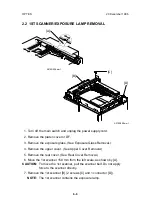
6. Move the 1st scanner 150 mm from the left scale, as shown by [A].
CAUTION: To move the 1st scanner, pull the scanner belt. Do not apply
force to the scanner directly.
7. Remove the 1st scanner [B] (2 screws [C] and 1 connector [D]).
NOTE: The 1st scanner contains the exposure lamp.
[A]
A219R508.wmf
[C]
[D]
[B]
A219R528.wmf
OPTICS
20 December 1996
6-6
Summary of Contents for FT 4015
Page 2: ...SECTION 1 OVERALL MACHINE INFORMATION...
Page 14: ...SECTION 2 DETAILED DESCRIPTIONS...
Page 71: ...SECTION 3 INSTALLATION...
Page 90: ...SECTION 4 SERVICE TABLES...
Page 118: ...SECTION 5 PREVENTIVE MAINTENANCE...
Page 126: ...SECTION 6 REPLACEMENT AND ADJUSTMENT...
Page 190: ...SECTION 7 TROUBLESHOOTING...
Page 222: ...SECTION 8 OPTIONS...
Page 223: ...SECTION 9 APPENDIX TIMING CHART...
Page 225: ...COPIER A219 ELECTRICAL COMPONENT LAYOUT 4 2 3 1 5 6 A219S500 wmf...
Page 226: ...10 15 14 13 12 11 9 8 7 18 17 16 A219S501 wmf...
Page 227: ...24 40 23 28 27 26 25 19 20 21 22 29 39 31 32 33 34 35 36 38 37 30 A219S502 wmf...


