


Mode No.
Function
Settings
59
Optics
Temperature
Display
✝
Displays the optics temperature detected by the
optics thermistor.
Press the
key to monitor the temperature
during the normal copy cycle.
60
Drum Potential
Measurement
(With Paper)
Factory use only.
61
Drum Potential
Measurement
(Without
Paper)
Factory use only.
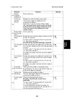
62
V
L
Correction
Interval
Sets the interval for V
L
correction. The exposure
lamp voltage (SP48) is increased by 1 step at the
set copy count interval.
1 step of the lamp voltage equals 0.5 V for
N-American, and 1.0 V for European machines.
0 ~ 8
Default = 2
See "Detailed Section Descriptions - Exposure
Lamp Voltage Control" for details.
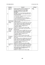
63
Forced Toner
Supply
Forces the toner bottle to supply toner to the
development unit.
0: 6 seconds
1: 3 seconds
This mode starts when the
key is pressed,
and stops automatically after the selected time.
Use this mode to achieve standard image
density when copy quality problems indicate
low toner.
64
V
R
Correction
Value
Sets the V
R
correction value.
Keep this at the default setting.
Default = 0
66
TD Sensor
Initial Setting
Performs the TD sensor initial setting.
This SP mode controls the voltage applied to the TD
sensor to make the TD sensor output 1.9
±
0.1 V.
After using SP66, check SP67 to see if the sensor is
working correctly.
This mode is started by pressing the
key
and stops automatically after about 1 minute.
Use this mode only after installing new
developer.
67
TD Sensor
Initial Output
Display
Display the TD sensor initial setting output.
(0.02 V x
displayed
value)
SP Setting
Exposure Lamp
Note
0
+2 steps/8,000 copies
1
+2 steps/6,000 copies
2
+2 steps/4,000 copies
Default
3
+2 steps/2,000 copies
4
+2 steps/1,000 copies
5
No Correction
Service
Tables
20 December 1996
PROGRAM MODES
4-19
Summary of Contents for FT 4015
Page 2: ...SECTION 1 OVERALL MACHINE INFORMATION...
Page 14: ...SECTION 2 DETAILED DESCRIPTIONS...
Page 71: ...SECTION 3 INSTALLATION...
Page 90: ...SECTION 4 SERVICE TABLES...
Page 118: ...SECTION 5 PREVENTIVE MAINTENANCE...
Page 126: ...SECTION 6 REPLACEMENT AND ADJUSTMENT...
Page 190: ...SECTION 7 TROUBLESHOOTING...
Page 222: ...SECTION 8 OPTIONS...
Page 223: ...SECTION 9 APPENDIX TIMING CHART...
Page 225: ...COPIER A219 ELECTRICAL COMPONENT LAYOUT 4 2 3 1 5 6 A219S500 wmf...
Page 226: ...10 15 14 13 12 11 9 8 7 18 17 16 A219S501 wmf...
Page 227: ...24 40 23 28 27 26 25 19 20 21 22 29 39 31 32 33 34 35 36 38 37 30 A219S502 wmf...


