background image

©2021 Alamo Group Inc.

TR308

Published 04/21

Part No. 00793560C

RHINO

®


1020 S. Sangamon Ave.

Gibson City, IL 60936

800-446-5158

Email: [email protected]
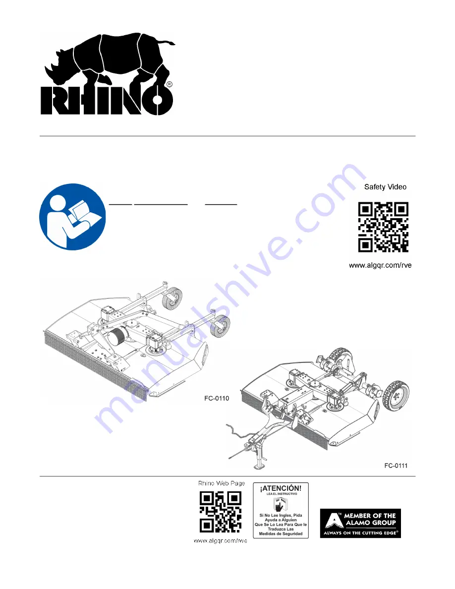
ROTARY MOWER

OPERATOR’S MANUAL

This Operator's Manual is an integral part of the safe operation of 

this machine and must be maintained with the unit at all times.  

READ, UNDERSTAND, and FOLLOW the Safety and Operation 

Instructions contained in this manual before operating the 

equipment. 

C01-Cover_Rstr

Important Operating and Safety Instructions are found in the Mower 

Safety Video that can be instantly accessed on the internet at: 

www.algqr.com/rve 

Summary of Contents for FC-0110

Page 1: ... Manual is an integral part of the safe operation of this machine and must be maintained with the unit at all times READ UNDERSTAND and FOLLOW the Safety and Operation Instructions contained in this manual before operating the equipment C01 Cover_Rstr Important Operating and Safety Instructions are found in the Mower Safety Video that can be instantly accessed on the internet at www algqr com rve ...

Page 2: ......

Page 3: ...manual or if you have any questions concerning safety of operation contact your supervisor dealer or Alamo Group Ag If you would like a VHS video tape of the video please email AEMVideo alamo group com or Fax AEM VHS Video at 830 372 9529 or mail in a completed copy of the form on the back of this page to AEM VHS Video 1502 E Walnut Street Seguin TX 78155 and request the VHS video version Please i...

Page 4: ..._________________________ City _________________________________________ State ________________________________________ Zip Code _____________________________________ Mower Model __________________________________ Serial Number ____________________________________ Date Purchased _________________________________ Dealer Salesperson ________________________________ Dealership Name __________________...

Page 5: ...e the chance of accidents SAFETY FIRST Completely read and understand the safety section of this manual before operating this equipment Do not allow anyone to operate this equipment who has not fully read and understood this manual Contact your Dealer to explain any instructions that you do not fully understand The care you give your Rhino Implement will greatly determine your satisfaction with it...

Page 6: ... that operator is responsible for keeping clear of such hazards PRE DELIVERY SERVICE CHECK AND ADJUST OR LUBRICATE AS REQUIRED See Operator s Manual for Details Inspection Performed Warranty and Safety Procedures Explained Installation Complete LUBRICATION HYDRAULICS MOWER TO TRACTOR CONNECTIONS Gearbox Oil Levels Draw Bar Length Check And Set Hydraulic Oil Level External Tank A Frame Pivot Links ...

Page 7: ...ION PULL TYPE 1 19 DECAL DESCRIPTION 1 21 FEDERAL LAWS AND REGULATIONS 1 30 INTRODUCTION SECTION 2 1 KEY OPERATION POINTS 2 4 Operating Noise Level Sound Pressure 2 4 Warranty information 2 4 ASSEMBLY SECTION 3 1 DEALER SETUP INSTRUCTIONS 3 2 TAIL WHEEL ASSEMBLY LIFT 3 4 TONGUE 3 4 AXLE ASSEMBLY PULL TYPE 3 5 AXLE ARM 3 5 CUTTER LEVELING 3 6 AXLE ASSEMBLY SEMI MOUNT 3 7 LEVEL RODS PULL TYPE 3 7 DR...

Page 8: ...Height Lift Type 4 13 Setting Mowing Height Pull and Semi Mount Type Mowers 4 14 Setting Deck Pitch 4 15 DRIVELINE ATTACHMENT 4 15 Driveline Length Check 4 16 Constant Velocity CV Driveline 4 18 PRE OPERATION INSPECTION AND SERVICE 4 19 Tractor Pre Operation Inspection Service 4 20 Mower Pre Operation Inspection Service 4 20 Cutting Component Inspection 4 23 Blade Bolt Inspection 4 26 Driving The ...

Page 9: ... JACKSHAFT DRIVELINE SHIELD 5 9 MAIN CV DRIVELINE SAFETY SHIELD 5 10 TO DISASSEMBLE UNIVERSAL JOINT 5 11 TO REASSEMBLE UNIVERSAL JOINT 5 12 DRIVELINE TAPER CONE YOKE REMOVAL INSTRUCTIONS 5 14 BLADE SERVICING 5 14 BLADE SHARPENING 5 15 BLADE CARRIER REMOVAL 5 16 BLADE CARRIER INSPECTION 5 16 BLADE CARRIER INSTALLATION 5 17 BLADE REMOVAL 5 17 BLADE TIMING AND ROTATION 5 18 Blade Timing Procedure 5 1...

Page 10: ......

Page 11: ...Safety Section 1 1 2021 Alamo Group Inc SAFETY SECTION ...

Page 12: ... is up to YOU Only YOU can prevent death or serious injury from unsafe practices Indicates a hazardous situation that if not avoided WILL result in DEATH OR VERY SERIOUS INJURY Indicates a hazardous situation that if not avoided COULD result in DEATH OR SERIOUS INJURY Indicates a hazardous situation that if not avoided MAY result in MINOR OR MODERATE INJURY Identifies special instructions or proce...

Page 13: ...T prolonged operation can cause fatigue STOP and REST GENERAL OPERATING SAFETY VISIBILITY CONDITIONS WHEN MOWING OPERATE IN DAYLIGHT or with lights that gives at least 100 yards clear visibility BE ABLE TO SEE and identify passersby steep slopes ditches drop offs overhead obstructions power lines debris and foreign objects GROUND SPEED WHEN MOWING NORMAL SPEED range is between 2 to 5mph ADJUST MOW...

Page 14: ...king collar to ensure it freely slides on PTO shaft SECURELY seat yoke locking balls in PTO shaft groove PUSH and PULL DRIVELINE on both the tractor and implement PTO SHAFTS to ensure it is SECURELY ATTACHED TO AVOID broken driveline during operations CHECK driveline for proper length between PTO shaft and implement gearbox shaft Drivelines too short can pull apart or disengage Drivelines too long...

Page 15: ...rom mechanical or hydraulic failure or inadvertent Control Lever movement TO AVOID EQUIPMENT FALLING while working near or under lifted wings components and implements raised by 3 Pointed tractor hitch SECURELY SUPPORT or block up raised equipment and components BLOCK UP and securely support equipment before putting hands feet or body under raised equipment or lifted components WHEN PARKING Implem...

Page 16: ...1 MARK objects that cannot removed 2 AVOID these objects when mowing HIGH GRASS and WEED AREA INSPECTION INSPECT for and REMOVE any hidden large debris MOW at Intermediate height INSPECT and remove remaining debris MOW at final height MOWER THROWN OBJECT SHIELDING KEEP all thrown object shielding including Front and Rear Deflectors Chains Guards Steel Guards Bands Side Skirts and Skid Shoes in pla...

Page 17: ... STOP MOWING immediately if blades strike heavy objects fixed structures metal guard rails and concrete structures 1 BLADES CAN FAIL from impact and objects can be thrown with great velocity 2 INSPECT and REPLACE any damaged blades 3 CHECK blade carrier balance and REPLACE if damaged DO NOT mow in standing water TO AVOID possible BLADE FAILURE AVOID MOWING in reverse 1 STOP PTO and back up mower 2...

Page 18: ... start tractor while seated in tractor seat ALWAYS BUCKLE UP seat belt when operating tractor and equipment ONLY OPERATE tractor and equipment while seated in tractor seat NEVER ALLOW RIDERS on tractor or implement WHEN MOUNTING AND DISMOUNTING TRACTOR ONLY mount or dismount when tractor and moving parts are stopped STOP ENGINE AND PTO engage parking brake lower implement allow all moving parts to...

Page 19: ...sing ALWAYS REPLACE GUARDS that have been removed for service or maintenance Do Not use PTO or PTO guard as a step TO AVOID broken driveline during operations CHECK driveline for proper length between PTO shaft and implement gearbox shaft Refer to Instructions in Operation Section Drivelines too short can pull apart or disengage Drivelines too long can bottom out Bottoming driveline telescoping as...

Page 20: ...P LOOK and LISTEN before approaching the mower to make sure all rotating motion has stopped IF A MATERIAL BLOCKAGE occurs in the inlet or discharge areas of the mower SHUT DOWN TRACTOR ENGINE disengage the PTO and wait for all rotating motion to stop Place the tractor in park position engage the parking brake and remove the key before leaving the operator s set Clear the blockage before proceeding...

Page 21: ...g on the system REMOVE and replace hose if you suspect it leaks Have dealer test it for leaks HIGH PRESSURE FLUID LEAKS CAN BE INVISIBLE WHEN CHECKING FOR HYDRAULIC LEAKS AND WORKING AROUND HYDRAULIC SYSTEMS ALWAYS WEAR safety glasses with side shields marked with ANSI Z87 and impenetrable gloves USE paper or cardboard to search for leaks DO NOT USE hands or body parts to search for leak KEEP hand...

Page 22: ... 0808 for identify buried utility lines FIRE PREVENTION GUIDELINES while Operating Servicing and Repairing Mower and Tractor to reduce equipment and grass fire Risk EQUIP Tractor with a FIRE EXTINGUISHER DO NOT OPERATE mower on a tractor equipped with under frame exhaust DO NOT SMOKE or have open flame near Mower or Tractor DO NOT DRIVE into burning debris or freshly burnt area AVOID FIRE IGNITION...

Page 23: ...UST your operating position mirrors and implement transport for clear vision for traveling and traffic conditions PREPARE IMPLEMENT FOR TRANSPORTING OR TOWING DISENGAGE PTO RAISE MOWER REMOVE any cut material collected on mower deck TOWED MOWERS ENGAGE TRANSPORT LOCKS AND SAFETY CHAINS INSTALL center axle cylinder transport stops or pins ATTACH implement SAFETY CHAIN to tractor DETERMINE STOPPING ...

Page 24: ...IMPLEMENT driveline from tractor PTO Shaft WEAR SAFETY GLASSES PROTECTIVE GLOVES and follow SAFETY PROCEDURES when performing service repairs and maintenance on the implement Always WEAR protective GLOVES when handling chemicals or worn component with sharp edges Always WEAR GLOVES and SAFETY GLASSES when servicing components AVOID CONTACT with hot hydraulic oil tanks pumps motors valves and hose ...

Page 25: ...r broken parts with authorized service parts LUBRICATE unit as specified by lubrication schedule NEVER lubricate adjust or remove material while it is running or in motion TORQUE all bolts and nuts as specified BLADE INSPECTION REPLACE bent damage cracked or broken blades immediately with new blades AVOID blade failures and thrown broken blades DO NOT straighten weld or weld hard facing blades SAF...

Page 26: ...s knives knife hangers rollers drivetrain components and bearings These parts are made and tested to Rhino specifications Non genuine will fit parts do not consistently meet these specifications The use of will fit parts may reduce mower performance void warranties and present a safety hazard Use genuine Rhino mower parts for economy and safety SPRM 1 str SEE YOUR RHINO DEALER ...

Page 27: ...o promote safe operation Damage to the decals may occur while in shipping use or reconditioning Rhino cares about the safety of its customers operators and bystanders and will replace the safety decals on this product in the field free of charge Some shipping and handling charges may apply Contact your Rhino dealer to order replacement decals ...

Page 28: ...ORMATION Flag Made in U S A 10 D137 1 INSTRUCT CCW Blade Rotation 11 D138 1 INSTRUCT CW Blade Rotation 12 D534 2 WARNING Blade Attachment 13 00793532 3 WARRANTY Gearbox Warranty 14 00756004 3 DANGER Shield Missing 15 D388 1 DANGER Driveline Hazard 16 D614 3 DANGER Thrown Object Shield Missing 17 D454 1 WARNING Crushing Hazard Under Deck 18 D389 1 DANGER Multi Hazard 19 00760657 1 WARNING Genuine R...

Page 29: ...o promote safe operation Damage to the decals may occur while in shipping use or reconditioning Rhino cares about the safety of its customers operators and bystanders and will replace the safety decals on this product in the field free of charge Some shipping and handling charges may apply Contact your Rhino dealer to order replacement decals ...

Page 30: ...lade Rotation 12 D534 2 WARNING Blade Attachment 13 00793532 3 WARRANTY Gearbox Warranty 14 00756004 3 DANGER Shield Missing 15 D388 1 DANGER Driveline Hazard 16 D614 3 DANGER Thrown Object Shield Missing 17 D454 1 WARNING Crushing Hazard Under Deck 18 D389 1 DANGER Multi Hazard 19 00760657 1 WARNING Genuine Rhino Parts 20 D608 2 WARNING Blade Timing 21 D518 1 WARNING Jack Capacity 22 D390 1 DANGE...

Page 31: ...SAFETY TR308 04 21 Safety Section 1 21 SAFETY 2021 Alamo Group Inc DECAL DESCRIPTION ...

Page 32: ...SAFETY SAFETY TR308 04 21 Safety Section 1 22 2021 Alamo Group Inc ...

Page 33: ...SAFETY TR308 04 21 Safety Section 1 23 SAFETY 2021 Alamo Group Inc ...

Page 34: ...SAFETY SAFETY TR308 04 21 Safety Section 1 24 2021 Alamo Group Inc ...

Page 35: ...SAFETY TR308 04 21 Safety Section 1 25 SAFETY 2021 Alamo Group Inc ...

Page 36: ...SAFETY SAFETY TR308 04 21 Safety Section 1 26 2021 Alamo Group Inc ...

Page 37: ...SAFETY TR308 04 21 Safety Section 1 27 SAFETY 2021 Alamo Group Inc ...

Page 38: ...SAFETY SAFETY TR308 04 21 Safety Section 1 28 2021 Alamo Group Inc ...

Page 39: ...SAFETY TR308 04 21 Safety Section 1 29 SAFETY 2021 Alamo Group Inc ...

Page 40: ...ect the power source and wait for all machine movement to stop before servicing adjusting cleaning or unclogging the equipment except where the machine must be running to be properly serviced or maintained in which case the employer shall instruct employees as to all steps and procedures which are necessary to safely service or maintain the equipment Make sure everyone is clear of machinery before...

Page 41: ...Introduction Section 2 1 2021 Alamo Group Inc INTRODUCTION SECTION ...

Page 42: ...is 100 effective in preventing thrown objects The possibility of injury and property damage from this hazard can be substantially reduce by selecting proper shielding maintaining the mower and shielding in good operational condition inspecting the area for foreign debris before mowing operating the mower at a minimum cutting height of 4 and keep unprotected persons at a minimum distance of 300 fee...

Page 43: ...ched to the tractor using 3 point Cat II standard or CAT II III quick hitches or pull drawbar Standard equipment includes driveline shields clutch shields and front and rear discharge shields Equipment Specifications Cutting Width 98 Blade Tip Speed Transport Width 103 540 RPM 16 512 FPM Overall Width 103 1000 RPM 16 378 FPM Overall Length 94 1 2 Lift 97 Semi 143 Pull Gearbox Rating Cutting Height...

Page 44: ...ications Warranty information In addition to the standard Limited Warranty shown on the facing page Rhino also provides 1 A SIX YEAR 72 months LIMITED WARRANTY on GEARBOX components provided they have been properly maintained and have not been subjected to abuse or mis use except as limited below WARRANTY LIMITATIONS GEARBOX A Warranty is ONE YEAR 12 MONTHS for Seals After one year seals are consi...

Page 45: ...cturer 2 05 Purchaser is responsible for any labor charges exceeding a reasonable amount as determined by Manufacturer and for returning the goods to the Dealer whether or not the claim is approved Purchaser is responsible for the transportation cost for the goods or part s from the Dealer to the designated factory 3 LIMITATION OF LIABILITY 3 01 MANUFACTURER DISCLAIMS ANY EXPRESS EXCEPT AS SET FOR...

Page 46: ......

Page 47: ...Assembly Section 3 1 2021 Alamo Group Inc ASSEMBLY SECTION ...

Page 48: ...ely remove the shipping stand first attach the lifting straps to the two 1 bolts and the forks of the lift truck as seen in picture Once you have the cutter secured with the straps remove the two caster wheels and all the parts chain Guards rear brace and driveline etc that are attached to the shipping stand After you have removed these parts you will be able to see access the 2 bolts that connect...

Page 49: ...a 1 x 2 1 2 Hex Bolt 22 through the pivot hole on the A Frame Leg 1 2 and the inner hitch ears of the cutter deck as shown Secure with a 1 Toplock Nut 16 5 Connect the A Frame Legs 1 2 with a 1 x 5 Hex Bolt 15 passing though the upper hole of the Legs and the Bushing 14 as shown Secure with a 1 Toplock Nut 16 6 Connect the Floating Link 6 to the front A Frame Legs 1 2 by inserting a 3 4 x 4 1 2 Je...

Page 50: ... with two 1 2 x 1 1 2 Hex Bolts 7 and 1 2 Toplock Nuts 8 as shown TONGUE 1 Assemble tongue to cutter deck by aligning tongue 1 with hitch ear holes and inserting the tongue pins 4 through hitch ears and tongue bushings as shown Install 1 2 x 1 1 2 Hex Bolts 6 through the tongue pin flag and hitch ear and secure with 1 2 Toplock Nut 7 NOTE On left hand side of unit the 1 2 x 1 1 2 Hex Bolt 6 will g...

Page 51: ...OTE The Orientation of the Axle Arm Pin is important Retain the Axle Arm Pi by inserting a 5 16 x 2 1 4 Hex Bolt 12 through the bushing and pin and secure by installing a 5 16 Toplock Nut 13 3 Insert two 1 2 x 4 Hex Bolts 10 through the Suspension Axle Clamp 2 and then through two Rubber Suspension Pucks 5 Rotate the Suspension Axle Arm upward to align with the 1 2 x 4 Hex Bolts 10 Secure the arms...

Page 52: ... is on the low side of the cutter This cannot be done until the weight of the cutter is removed from the axle arm by placing a jackstand underneath the cutter and putting the hydraulic valve in the float position or loosening the ratchet hack if the hydraulic cylinder is not used which will then release pressure on the cylinder and the load on the axle arm Once this has been done the axle arm may ...

Page 53: ...2 Washer 11 and secure with 3 8 x 2 1 2 Cotter Pin 12 as Shown 3 Insert the Hub Spindle assembly 4 into the Castor 3 and secure with 1 2 x 3 1 4 Hex Bolt 13 and 1 2 Toplock Nut 8 LEVEL RODS PULL TYPE Attach the level rods to the lower lugs on tongue and to lugs on the rear axle tube using pins washers and cotter pins NOTE The adjusting nuts on control rods should be to rear of machine and should a...

Page 54: ...50 ft lb torque Push and pull the driveline to ensure it is securely attached to the shaft Regularly check the driveline yoke to ensure a tight connection To remove the yoke remove the bolt s and pull yoke off the shaft A two bolt yoke is shown in Figure Asm R 0472 Mower is now assembled and ready for pre delivery checks WHEELS Install the Wheels on the Wheel Hubs Note If Laminated Tires are used ...

Page 55: ...ing 1 2 x 1 1 2 Hex Bolts 2 1 2 Lockwashers 3 and 1 2 Flatwashers 4 as shown Place reflector bracket 5 between Chain Guard Assembly 1 and mower at outermost bolts as shown Rear Chain Guard Attach Center Chain Guard Assembly 1 and Outer Chain Guard Assemblies 5 to the mower using 1 2 x 1 1 2 Hex Bolts 2 1 2 Lockwashers 3 and 1 2 Flatwashers 4 as shown ...

Page 56: ...SIDE DRIVES LIFT PULL AND SEMI 1 Attach Drive Shield Support 2 to Divider Gearbox using 5 16 x 1 Hex Bolts 12 5 16 Lockwasher 13 and 5 16 Flatwasher 14 as shown 2 Use M8 x 20mm Hex Head Flange Bolts 3 to attach Hinge Mount Bracket 4 to Gearbox 10 3 Slide Brackets 5 and 6 onto Hinge Mount Bracket 4 as shown 4 Use 3 8 x 3 4 Carriage Bolts 8 3 8 Flatwashers 9 and 3 8 Acorn Nuts 10 to attach Driveline...

Page 57: ...and 5 16 Toplock Nut 8 as shown 3 Slide Brackets 9 10 onto Hinge Mount Bracket 1 as shown 4 Use 3 8 x 3 4 Carriage Bolts 11 3 8 Flatwashers 12 and 3 8 Acorn Nuts 13 to attach Driveline Shield 14 to Brackets 9 10 Leave Bolts loose 5 Attach Latch 15 to Driveline Shield 14 Close and latch Driveline Shield 14 against Bearing Mount Bracket 16 6 Tighten 3 8 Carriage Bolts 11 and Acorn Nuts 13 7 Attach G...

Page 58: ...neath side of the deck Use the adjustment slots vertically on the Bearing Mount 1 face and the adjustment slots on the bearing mounting plates to level the Jackshaft 3 vertical to reduce stress on the universal joint of the shaft NOTE Be certain to tighten all hardware to appropriate torque NOTE Two set screws on the flange bearing must be tightened after all of the 1 2 hardware HYDRAULIC OR MANUA...

Page 59: ...Operation Section 4 1 2021 Alamo Group Inc OPERATION SECTION ...

Page 60: ...ion of the Operator s Manual is designed to familiarize instruct and educate safe and proper mower use to the operator Pictures contained in this section are intended to be used as a visual aid to assist in explaining the operation of a rotary mower Some pictures may show shields removed for purposes of clarity NEVER OPERATE this implement without all shields in place and in good operational condi...

Page 61: ...nt PPE for the job conditions when attaching operating servicing and repairing the equipment PPE is designed to provide operator protection and includes the following safety wear PERSONAL PROTECTIVE EQUIPMENT PPE Always Wear Safety Glasses with side shields marked to comply with ANSI Z87 Hard Hat Steel Toe Safety Footwear Gloves Hearing Protection Close Fitting Clothing Respirator or Filter Mask d...

Page 62: ...Semi Mount 3 Point Hitch CAT II and CAT III Pull Type Mower Drawbar 14 extension for 540 RPM unit and 16 for 1000 RPM unit safety chain attachment point Front End Weight As needed to maintain 20 weight on front axle Power Take Off 540 RPM 6 spline or 1000 RPM 20 spline 1 3 4 diameter output shaft 2 1 ROPS and Seat Belt The tractor must be equipped with a Roll Over Protective Structure ROPS tractor...

Page 63: ... have adequate power may damage the tractor engine Exceeding 90 HP may cause mower damage by overpowering the unit in heavy cutting conditions 2 4 3 Point Hitch Lift Type and Semi Mount Type Mowers Lift Type Mower The tractor 3 point hitch must be rated to lift at least 2000 lbs The Model TR308 is designed to be mounted on a tractor with CATII or CATIII 3 point or CATII or CATIII Quick Hitch Refer...

Page 64: ...nual for instructions to change PTO speeds on models that operate at more than one speed If operating an older model tractor where the tractor s transmission and PTO utilize one master clutch an over running clutch must be used between the PTO output shaft and the driveline of the mower An authorized tractor dealer can provide the over running clutch and its installation if needed OPS U 0006 str D...

Page 65: ...e death or serious injury SG 12 str 3 1 Boarding the Tractor Use both hands and equipped handrails and steps for support when boarding the tractor Never use control levers for support when mounting the tractor Seat yourself in the operator s seat and secure the seat belt around you Never allow passengers to ride on the tractor or attached equipment Riders can easily fall off and be seriously injur...

Page 66: ...ut off control Locate the brake pedals and the clutch Locate the PTO control Locate the 3 point hitch control lever Locate the hydraulic remote control levers Before starting the tractor ensure the following Conduct all pre start operation inspection and service according to the tractor operator s manual Make sure all guards shields and other safety devices are securely in place The parking brake ...

Page 67: ...ositioned between the respective set of mower A frame lift lugs Note Set the 3 point lift control to Position Control so that the lift arms maintain a constant height when attaching the mower See the tractor Operator s Manual for correct settings when attaching 3 point equipment 4 Turn off the tractor engine and dismount 5 One lift arm at a time align arm end hole between the set of holes of A fra...

Page 68: ...oint lift controls while someone is directly behind the tractor 1 Make certain the implement s upper and lower hitch pins are secured 2 Lower the tractor s 3 point lift until the three Quick Hitch hooks are lower than the implements hitch pins Carefully back the tractor to align the Quick Hitch hooks under the implement s hitch pins 3 Slowly raise the tractor s 3 point lift until the lower Quick h...

Page 69: ...he mower hitch clevis Turn off the tractor engine set the parking brake place the tractor in park and dismount 4 To attach the mower place two 1 flatwashers 1 positioned under top lip of tongue clevis and to the top of drawbar Add additional 1 flatwashers 2 between the bottom of drawbar and bottom lip of clevis to fill open space Insert a 3 4 x 4 1 2 grade 5 or 8 bolt 3 through clevis and drawbar ...

Page 70: ...se damaged or deformed OPS U 0039 str IMPORTANT Scan this QR Code with your smart phone to link to the PAMI Safe Implement Hitching Manual for more information on correctly connecting agricultural tractors to implements Or type in your internet browser the following web address www algqr com hme Ops 0008 MISC str 6 SETTING THE MOWER Properly setting the cutting height is essential for efficient an...

Page 71: ...he lift arms is designed to allow for manipulation of its length Shortening or extending will allow for deck leveling from side to side 6 Securely block up the mower at this height 7 Remove the bolts securing the tailwheel beam support brackets and allow the tailwheel s to rest at ground level Align beam and positioning bracket holes with closest set of holes in support brackets and reinstall secu...

Page 72: ... stroke control spacers can be placed on the hydraulic shaft to maintain a set cutting height each time the mower is raised and lowered 3 Adjust the mower leveling rod so that the front of the mower is approximately 3 4 lower than the rear For semi mount units raise or lower 3 point lower links to set height of front of mower 3 4 lower than rear 4 If the mower is attached to a 3 point hitch drawba...

Page 73: ...low the mower to cut the grass twice and can result in a more even cut and improved distribution of the cut material IMPORTANT Adjust the leveling rods the same amount and maintain equal tension in the rods Improper adjust ment may cause rods to snap or bend Retighten the jamnuts after the deck pitch has been set OPS U 0041 str 7 DRIVELINE ATTACHMENT The driveline yoke and tractor PTO shaft must b...

Page 74: ...d through the support bearings or downward onto the PTO shaft breaking it off A broken driveline can cause personal injury S3PT 18 str When fitting the mower to the tractor the telescoping driveline must be inspected to ensure that at its most compressed position the profiles do not bottom out and when at its farthest extended position there is sufficient engagement between the profiles to operate...

Page 75: ...e With the driveline attached position the mower to the point where the telescoping driveline is at its maxi mum extension Completely shut down the tractor and secure in position Mark the inner driveline shield 1 8 from the end of the outer shield Disconnect the driveline from the tractor and separate the two driveline halves Measure the distance from the mark to the end of the inner profile This ...

Page 76: ...hard left turn until there is approximately a 1 clearance between the left rear tractor tire and mower frame or tongue Stop and completely shut down the tractor Place the tractor in Park and apply the Parking Brake before dismounting Check the CV joint at this maximum turning radius by holding the driveline yoke above the PTO shaft and then angle the CV joint to its maximum angle A minimum differe...

Page 77: ...oided OPS U 0029str Always disconnect the main PTO Driveline from the Tractor before performing service on the Implement Never work on the Implement with the tractor PTO driveline connected and running Rotating Parts Blades or Drivelines could turn without warning and cause immediate entanglement injury or death S3PT 11 str Never work under the Implement the framework or any lifted component unles...

Page 78: ...eering fluid level Fuel condition and level Sufficient lubrication at all lube points Air filter condition OPS U 0030 str 8 2 Mower Pre Operation Inspection Service Before each mower use a complete inspection and service is required to ensure the mower is in a good and safe working condition Damaged and or broken parts should be repaired and or replaced immediately To ensure the mower is ready for...

Page 79: ...tch bolt is the cor rect size that washers are inserted between the drawbar and hitch clevis and the locknut is securely tightened OPS R 0008_D str Ensure deflectors and or chainguards are in position and not damaged Replace worn broken and missing pieces OPS R 0038_F str All Safety Shields Guards and Safety devices including but not limited to the Deflectors Chain Guards Steel Guards Gearbox Shie...

Page 80: ...sure the tractor PTO master shield and the mower slip clutch shield are in place low ered and in good condition Ensure the driveline integral shield is in good condition and rotates freely Ensure the driveline slip clutch if equipped is properly adjusted OPS R 0039_O str Perform scheduled lubrication as specified in the maintenance section Inspect each gearbox oil level using dipstick level indica...

Page 81: ...ged worn and missing blades as complete sets to maintain rotary balance during operation Ensure blade pan nut is tightened with the cotter pin inserted and spread Ensure the blade carriers are properly timed to avoid blade contact during operation See instructions to properly time blades in the Maintenance Section OPS R 0041 _B str 8 3 Cutting Component Inspection Inspect blade pan and blade assem...

Page 82: ...wer for distances up to 300 feet When the blades are replaced the fasteneing hardware must be replaced Check and retightenthe blade hardware after the first eight hours of operation In severe cutting conditions recheck the blade carrier and blade bolt torque every 50 hours To prevent structural damage caused by loose hardware tighten gearbox mounting hardware as specified Check the fastener torque...

Page 83: ...pe or Any cracks are visible or Deep gouges in the blade s surface are present or Gouges or chipped areas in the cutting edge are larger than 1 2 12 7mm or The material on the leading edge has been worn away by more than 1 2 12 7mm Failure to replace abnormally worn blades may lead to catastrophic failure of the blades and ejection of the broken part with tremendous force which may cause serious b...

Page 84: ...ling when the blades and or carrier are being serviced Visible cracks or If the recessed area on blade bolt is worn off or If Blade Bolt has gouges or chipped areas Failure to replace abnormally worn blade bolts may lead to catastrophic failure of the blades and ejection of the broken part which may cause serious bodily injury or death Always replace Blade Bolts with new bolts whenever replacing t...

Page 85: ...rt of Shift SpecificComments if not OK The flashing lights function properly The SMV Sign is clean and visible The tires are in good condition with proper pressure The wheel lug bolts are tight The tractor brakes are in good condition The steering linkage is in good condition There are no visible oil leaks The hydraulic controls function properly The ROPS or ROPS Cab is in good condition The seatb...

Page 86: ...e The tongue hitch connection bolts and pins are tight There are no cracks in tongue or hitch The tow chain is secured to the tractor and mower The hydraulic cylinder pins are tight There are no leaking or damaged hoses The mower deck is clear of cut grass and debris Chain guards deflectors are in place and in good condition Driveline gearbox shields are in good condition Driveline clutches are in...

Page 87: ...eds for you and the equipment Make sure you abide by the following rules Test the tractor at a slow speed and increase the speed slowly Apply the Brakes smoothly to determine the stopping characteristics of the Tractor and Implement As you increase the speed of the Tractor the stopping distance increases Determine the maximum transport speed not to exceed 20 mph 30 kph for transporting this equipm...

Page 88: ...ked together to provide simultaneous rear wheel braking FOR MOST DRIVING AND OPERATING CONDITIONS THE BRAKE PEDALS SHOULD BE LOCKED TOGETHER TO PROVIDE THE MOST EFFECTIVE BRAKING ACTION Always disengage the tractor differential lock when turning When engaged the differential lock will prevent or limit the tractor from turning During normal cutting conditions locking the differential provides no be...

Page 89: ...hould never be operated at speeds that cannot be safely handled or which will prevent the operator from stopping quickly during an emergency If the power steering or engine ceases operating stop the tractor immediately as the tractor will be difficult to control Perform turns with the tractor and mower at slow speeds to determine how the tractor with an attached mower handles a turn Determine the ...

Page 90: ...ious damage to the tractor and mower drive by pushing the PTO into the tractor and through the support bearings or downward onto the PTO shaft breaking it off Damage resulting from over collapse of the driveline s inner profile and its outer housing may allow the driveline to come loose from the Tractor which could cause bodily injury to the operator or bystanders and or extensive damage to the Tr...

Page 91: ...ed to any operator who cannot read Never allow someone to operate the implement and tractor without complete operating instructions Before starting any operation the operator must become familiar with the area to be worked in and any obstacles and hazards contained within to ensure safety to the operator bystanders and equipment Special attention should be paid to foreign debris rough terrain stee...

Page 92: ...ition of the mower and make any needed repairs immediately Make sure the blades are not damaged and the carrier is balanced before resuming operation Always wear your seat belt securely fastened and only operate the tractor and mower with the ROPS in the raised position If the tractor or mower hits a tree stump rock or bump a sudden movement could throw you off of the seat and under the tractor an...

Page 93: ...n spread cut material better reduce streaking and make the final cut more uniform SRM 01 str 10 3 Engaging the Power Take Off PTO Before engaging the PTO make certain that the area is clear of bystanders and passersby The implement must be completely lowered and the deck positioned at a safe operating height NEVER engage the PTO with the implement in the raised position Set the tractor engine spee...

Page 94: ...er lines or when debris and foreign objects are to be avoided SGM 07 str 10 5 Operating the Mower The mower is designed to cut vegetative material up to 2 1 2 in diameter Travel at a speed that allows the mower sufficient time to cut through the vegetation and maintain the operating speed at 540 rpm to prevent overloading the mower and tractor and to produce a clean cut Choose a driving pattern th...

Page 95: ...to burning debris or freshly burnt areas Ensure slip clutches are properly adjusted to prevent excessive slippage and plate heating Never allow clippings or debris to collect near drivelines slip clutches and gear boxes Periodically shut down the Tractor and Mower and clean clippings and collected debris from the mower deck SGM 12 str When you get to the end of a pass slightly raise the mower 2 4 ...

Page 96: ...passes to achieve a uniform cut In such conditions raise the cutting height to 12 or more on the first pass OPS R 0043 str Then lower the mower to the desired height and mow the vegetation a second time If possible select a mowing pattern that is at a 90 degree angle to the first pass to reduce streaking for a more uniform cut OPS R 0044 str ...

Page 97: ...to REMOVE potential THROWN OBJECT HAZARDS 6 NEVER ALLOW BLADES to CONTACT SOLID OBJECTS like wire rocks posts curbs guardrails or ground while mowing ROTARY MOWERS CAN THROW OBJECTS 300 FEET OR MORE UNDER ADVERSE CONDITIONS TO AVOID SERIOUS INJURY OR DEATH TO OPERATOR OR BYSTANDERS FROM THROWN OBJECTS INSPECT AREA FOR POTENTIAL THROWN OBJECTS BEFORE MOWING REMOVE debris rocks wire cable metal obje...

Page 98: ...and apply the parking brake lower the attached implement to the ground shut down the engine remove the key and wait for all motion to come to a complete stop before exiting the tractor OPS U 0016 str 11 DISCONNECTING THE MOWER FROM THE TRACTOR Before disconnecting the mower the PTO must be disengaged and blade rotation at a complete stop Move the mower to a level storage location and lower it to t...

Page 99: ... the mower Next remove both lower hitch pins Semi Mount Mower To disconnect the mower first remove hydraulic pressure by moving the control lever back and forth several times Next remove both lower lift arms and the hydraulic hose Pull Type Mower To disconnect the mower first relieve hydraulic pressure by moving the control lever back and forth several times Lower the parking jack and raise the mo...

Page 100: ... season Store the mower in a clean dry place with the mower housing resting securely on blocks or at ground level Keep the driveline yoke from sitting in water dirt and other contaminants Use spray touch up enamel where necessary to prevent rust and maintain the appearance of the mower It is critical that driveline clutches slip when an obstacle or heavy load is encountered to avoid mower and or t...

Page 101: ...substantially minimized OPS U 0017str Before transporting the tractor and mower idle the tractor engine disengage the PTO and wait for all mower moving parts to come to a complete stop Once all mower parts are completely stopped raise the mower to transport height NOTE When raising the mower maintain 1 clearance between the driveline and mower deck If additional mower deck height is needed for saf...

Page 102: ...rd applications of the tractor brakes when towing heavy loads at road speeds Never tow the implement at speeds greater than 20 MPH 32 kph OPS U 0018str 13 1 Tires and Wheels Laminated Sectional Tires are designed for conditions where puncture proof performance is required and the mower will not be transported for long distances on roadways Transport speed for laminated tires should not exceed 20 M...

Page 103: ...e certain that the Slow Moving Vehicle SMV sign is installed in such a way as to be clearly visible and legible When transporting the Equipment use the Tractor flashing warning lights and follow all local traffic regulations SG 6 str The SMV Slow Moving Vehicle emblem is universal symbol used to alert drivers of the presence of equipment traveling on roadways at a slow speed SMV signs are a triang...

Page 104: ...at will be traveled through Use adequately sized and rated trailers and equipment to transport the tractor and implement Consult an authorized dealer to determine the proper equipment required Using adequately sized chains heavy duty straps cables and or binders securely tie down both the front and rear of the tractor utilizing the proper tiedown locations as specified by the tractor manufacturer ...

Page 105: ...uce ground speed RPM too low Use full PTO speed Refer to your tractor Operator s Manual Improper blade for direction of cut Install blades so rotation is correct Poor Shredding Excessive ground speed Raise the front of Mower relative to the rear to hold and circulate material longer Refer to the Operation Section Setting the Mower Setting Deck Height Reduce ground speed Cutting too high Lower cutt...

Page 106: ...ns too wet for cutting Allow grass to dry before cutting Blades unable to cut that part of grass pressed down by path of tractor tires Slow ground speed of tractor but keep engine running at full PTO wpm Dull blades Sharpen or replace blades Height of cutter lower at rear or front See Cutting Height Instructions Gearbox Overheating Low on lubricant Fill to level plug Improper type lubricant Replac...

Page 107: ...Maintenance Section 5 1 2021 Alamo Group Inc MAINTENANCE SECTION ...

Page 108: ...any work procedures USE ladder or raised stands to reach high equipment areas inaccessible from ground ENSURE good footing by standing on solid flat surfaces when getting on implement to perform work FOLLOW manufacturer s instructions in handling oils solvents cleansers and other chemical agents DO NOT change any factory set hydraulic calibrations to avoid component or equipment failures DO NOT mo...

Page 109: ...ong life and trouble free operation Always disengage the PTO before raising the Rotary Cutter for transporting or making adjustments NOTE Some guards and shields have been removed from the illustrations and pictures for instructional clarity DO NOT operate implement without all shields and guards in place and in good condition LUBRICATION Do not let excess grease collect on or around parts particu...

Page 110: ...MAINTENANCE TR308 04 21 Maintenance Section 5 4 MAINTENANCE 2021 Alamo Group Inc ...

Page 111: ...MAINTENANCE TR308 04 21 Maintenance Section 5 5 MAINTENANCE 2021 Alamo Group Inc ...

Page 112: ...MAINTENANCE TR308 04 21 Maintenance Section 5 6 MAINTENANCE 2021 Alamo Group Inc ...

Page 113: ... quarts and the center gearbox has a five quart capacity NOTE Overfilling the Gearbox will cause pressure to build up and cause Oil Seals to leak ATTENTION If the Gearbox suddenly starts making an unusual noise stop at once check for leaks Once located correct the source of noise TAIL WHEEL ASSEMBLY Tail Wheel Bearings are packed at the factory with heavy duty bearing grease Grease Fittings are pr...

Page 114: ...the hole in the Shield matches up with the Grease Fitting Lubricate all fittings with a good quality Lithium Soap compatible E P grease meeting the N L G I 2 specifications and containing no more than 1 Molybdenum Disulfide An E P grease meeting the N L G I 2 specifications and containing 3 Molybdenum Disulfide may be substituted in the telescoping members only Inspect the U Joint for wear by hold...

Page 115: ...es do not telescope properly or show signs of abnormal wear the shaft should be repaired or replaced To assemble the main inner driveline shield grease the yoke groove and inner profile tube Attach the bearing ring in groove with recesses facing profile tube FIGURE Mnt 0027 Slide on the half shield Turn the cone until it engages correctly Install locking screws FIGURE Mnt 0028 IMPORTANT Scan this ...

Page 116: ...semble outer CV driveline grease yoke groove and inner profile tube Attach bearing ring on groove with recesses facing profile tube Slide on half shield with cone Turn cone until it engages correctly Tighten locking screws Grease bearing groove in double yokel Insert bearing ring Slide guard cone for double yoke over cam from the connecting end Make sure holes for screws are visible Tighten lockin...

Page 117: ... strike top arm of unsupported yoke to drive the top cup up Repeat on opposite side 3 If you cannot grip the loosened cap per Step 4 use a pointed tool to tip a needle them repeat Step 2 4 Grip loosened cup in vise strike yoke arm to drive yoke off cup Repeat on opposite cup 5 Support cross in loose vise and strike yoke arm Repeat Step 4 to remove remaining two cups ...

Page 118: ...oup Inc TO REASSEMBLE UNIVERSAL JOINT 1 Smear grease into bearings and check for dirt CAUTION Make sure all needle bearings are seated properly 2 Insert cup and cross Drive in with spacer 3 Insert snap ring 4 Insert second cup and hold cross into cup Drive cup flush with arm ...

Page 119: ... 13 MAINTENANCE 2021 Alamo Group Inc 5 Drive cup down with spacer and insert snap ring 6 To loosen cross strike yoke arm and check cross for free rotation 7 Position second yoke on cross Repeat Steps 2 to 6 8 Grease kit after assembly is completed ...

Page 120: ... or broken blade with new blades NEVER ATTEMPT TO STRAIGHTEN OR WELD ON BLADES SINCE THIS WILL LIKELY CRACK OR OTHERWISE DAMAGE THE BLADE WITH SUBSEQUENT FAILURE AND POSSIBLE SERIOUS INJURY FROM THROWN BLADES SGM 10 Manually wiggle the blade carriers to check for any looseness Retighten any loose parts Recheck torque every 50 hours Operating with loose blade hardware will damage the blade holder a...

Page 121: ...r no more than 1 2 notch wear BLADE SHARPENING When sharpening blades grind each blade the same amount to maintain balance Follow original sharpening pattern as shown in Figure Mnt R 0008 Always sharpen blades by grinding Always sharpen both blades at same time to maintain balance The difference in blade weights should not exceed 1 ounce Unbalanced blades will cause excessive vibration which can d...

Page 122: ...blade bolt fit appears to be loose or sloppy measure the square hole in bushing If the bottom of the square hole is 1 16 or greater than the square shoulder of the new blade bolt the bushings should be replaced Bushings can be removed by cutting bushing head where it is welded to carrier bar Once head is removed bushing can be pressed out of bar Clean and grind top of blade bar so new bushing can ...

Page 123: ...ll the carrier with one hand while pulling and pushing with the other hand to try to rock or oscillate the blade carrier If the carrier is loose retighten the retaining nut before operating the mower Always recheck gearbox output shaft slotted blade carrier retaining nut torque after a few hours operation Avoid personal injury Do not work under cutter without support blocks to keep frame from fall...

Page 124: ...de while rotating FIGURE Mnt R 0102 Blade Timing Procedure 1 Raise the mower to minimum height to allow sufficient clearance between the mower deck and ground to visually inspect blade carriers 2 Completely shut down the tractor and secure the tractor in position by placing the tractor in park and setting the parking brake Securely block the mower at this height 3 On a side gearbox remove connecti...

Page 125: ... wrenches Friction Clutch Seasonal Maintenance To ensure proper clutch function after long periods of inactivity friction clutches should be run in to prevent oxidation build up The clutches are set to the proper torque setting from the factory Using the following procedure will provide the most accurate torque setting Procedure 1 Tighten the four nuts on inner bolt circle with either a 13 mm wren...

Page 126: ...s Make replacements immediately 5 Store the cutter in a clean dry place with the cutter housing resting on blocks 6 Use spray touch up enamel where necessary to prevent rust and maintain the appearance of the cutter PROPER TORQUE FOR FASTENERS The chart lists the correct tightening torque for fasteners When bolts are to be tightened or replaced refer to this chart to determine the grade of bolts a...

Page 127: ...MAINTENANCE TR308 04 21 Maintenance Section 5 21 MAINTENANCE 2021 Alamo Group Inc ...

Page 128: ...ly support the gearbox and subassemblies to prevent injuries to hands and feet due to inadvertent dropping or falling over Always wear safety glasses and gloves to prevent eye and hand injury when chiseling or hammering on metal components Hardened metal will chip unexpectedly An assembled gearbox is quite heavy Use a hoist or get help to handle them safely Lift carefully and properly using your l...

Page 129: ...RIPTION 1 2 Seal 2 2 Cap Side 3 1 Gear 14 Tooth 4 1 Spacer 5 2 Pip Plug 6 1 Shaft 7 1 Housing 8 4 Bearing 9 24 Lockwasher 10 24 Bolt 11 AR Gaskets including 0 40 0 25 0 30 12 1 Cap Hub Input 13 1 Adjusting Nut 14 1 Cotter Pin 15 1 Seal 16 1 Shaft 17 1 Gear 17 Tooth 18 1 Pipe Plug Vented not shown ...

Page 130: ... threaded end of shaft 16 to remove from hub Step IV Remove bearing cone 8 from shaft 16 Step V Remove bearing cups 8 from hub housing Step VI Remove 8 bolts 10 from on side cap 2 tap on opposite side shaft end 6 to remove side cap 2 and on side shaft assembly Step VII Remove 8 bolts retaining remaining side cap 2 in place Using end of hammer handle tap inside of cap to remove from main housing No...

Page 131: ... gear 3 Proper rolling torque should be 10 to 12 inch pounds If preload is to tight shims must be added under side cap opposite gear Input Hub Assembly Press bearing cups into hub making sure they are fully seated Press bearing cone onto shaft properly seated against shaft shoulder Assemble shaft into hub 12 add second bearing cone and gear Apply a thin coat of Liquid Lock such as Locktite 270 to ...

Page 132: ...RIPTION 1 2 Seal 2 2 Cap Side 3 1 Gear 14 Tooth 4 1 Spacer 5 2 Pip Plug 6 1 Shaft 7 1 Housing 8 4 Bearing 9 24 Lockwasher 10 24 Bolt 11 AR Gaskets including 0 40 0 25 0 30 12 1 Cap Hub Input 13 1 Adjusting Nut 14 1 Cotter Pin 15 1 Seal 16 1 Shaft 17 1 Gear 17 Tooth 18 1 Pipe Plug Vented not shown ...

Page 133: ...SEGURIDAD SEGURIDAD TR308 04 21 Safety Section 1 28 2021 Alamo Group ...

Page 134: ...SEGURIDAD TR308 04 21 Safety Section 1 27 SEGURIDAD 2021 Alamo Group ...

Page 135: ...SEGURIDAD SEGURIDAD TR308 04 21 Safety Section 1 26 2021 Alamo Group ...

Page 136: ...SEGURIDAD TR308 04 21 Safety Section 1 25 SEGURIDAD 2021 Alamo Group ...

Page 137: ...SEGURIDAD SEGURIDAD TR308 04 21 Safety Section 1 24 2021 Alamo Group ...

Page 138: ...SEGURIDAD TR308 04 21 Safety Section 1 23 SEGURIDAD 2021 Alamo Group ...

Page 139: ...SEGURIDAD SEGURIDAD TR308 04 21 Safety Section 1 22 2021 Alamo Group ...

Page 140: ...SEGURIDAD TR308 04 21 Safety Section 1 21 SEGURIDAD 2021 Alamo Group ...

Page 141: ...SEGURIDAD SEGURIDAD TR308 04 21 Safety Section 1 20 2021 Alamo Group ...

Page 142: ...SEGURIDAD TR308 04 21 Safety Section 1 19 SEGURIDAD 2021 Alamo Group ...

Page 143: ...SEGURIDAD SEGURIDAD TR308 04 21 Safety Section 1 18 2021 Alamo Group ...

Page 144: ...SEGURIDAD TR308 04 21 Safety Section 1 17 SEGURIDAD 2021 Alamo Group Descripción de Calcomanía ...

Page 145: ...probadas a la especificaciones de RHINO Partes que no son auténticas no regularmente llegan con estas especificaciones El uso de partes que no son auténticas puede reducir el funcionamiento de la cortadora anular garantias y presentar un peligro de seguridad Use partes de cortadora auténticas de RHINO por economía y seguridad SPRM 1 SP str CONTACTE A SU DISTRIBUIDOR RHINO NOTA Si necessita un manu...

Page 146: ...tal como se especifica en el cronograma de lubricación NUNCA lubrique ajuste o quite material mientras el equipo está en funcionamiento o movimiento AJUSTE todas las tuercas y pernos tal como se especifica INSPECCIÓN DE CUCHILLAS REEMPLACE las cuchillas dobladas dañadas agrietadas o rotas inmediatamente por cuchillas nuevas EVITE fallas de las cuchillas y que vuelen trozos de cuchillas NO enderece...

Page 147: ...I Z87 y GUANTES PROTECTORES y siga todos los PROCEDIMIENTOS DE SEGURIDAD al realizar tareas de servicio reparación y mantenimiento sobre el implemento Siempre USE GUANTES protectores al manipular las hojas cuchillas bordes filosos o un componente desgastado con bordes filosos Siempre USE GUANTES y GAFAS DE SEGURIDAD con protecciones laterales marcadas para cumplir con ANSI Z87 al reparar component...

Page 148: ...nto del tractor AJUSTE su posición de conducción los espejos y el transporte del implemento para tener una visión clara para condiciones de conducción y tránsito PREPARE EL IMPLEMENTO PARA EL TRANSPORTE O EL REMOLQUE DESAPLIQUE EL PTO ELEVE LA CORTADORA QUITE todo material cortado que se acumule en la plataforma de la cortadora CORTADORA AL REMOLQUE INSTALE TRABAS DE TRANSPORTE Y CADENA DE SEGURID...

Page 149: ...les de servicios subterráneos PAUTAS DE PREVENCIÓN DE INCENDIOS durante la operación reparación y servicio de la cortadora y el tractor a fin de reducir el riesgo de incendio del equipo y de la vegetación El tractor debe estar EQUIPADO CON MATAFUEGOS NO OPERE la cortadora sobre un tractor equipado con escape debajo del bastidor NO FUME ni acerque fuego directo a la cortadora o el tractor NO CONDUZ...

Page 150: ...E y reemplace la manguera si sospecha que tiene filtraciones Solicite al distribuidor que verifique si hay filtraciones LAS FILTRACIONES DE LÍQUIDO DE ALTA PRESIÓN PUEDEN NO SER VISIBLES AL VERIFICAR FILTRACIONES HIDRÁULICAS Y TRABAJAR CERCA DE LOS SISTEMAS HIDRÁULICOS SIEMPRE USE gafas de seguridad y guantes impenetrables USE papel o cartón para verificar si hay filtraciones NO USE las manos o pa...

Page 151: ...ONIDOS antes de acercarse a la cortadora para asegurarse de que se haya detenido todo el movimiento giratorio Si se produce un bloqueo de material en las áreas de entrada y descarga de la cortadora APAGUE EL MOTOR DEL TRACTOR desenganche la toma de fuerza y esperar a que todo movimiento de rotación se detenga Coloque el tractor en posición de estacionamiento ponga el freno de estacionamiento y ret...

Page 152: ...quitado para tareas de reparación o mantenimiento PARA EVITAR que la línea de conducción se rompa durante las operaciones VERIFIQUE que la línea de conducción tenga el largo adecuado entre el eje de PTO y el eje de la caja de cambios del implemento Las líneas de conducción demasiado cortas se pueden soltar o romper Las líneas de conducción demasiado largas pueden tocar el suelo Un ensamblaje teles...

Page 153: ...IENDA el tractor sentado en el asiento del tractor SIEMPRE ABRÓCHESE el cinturón de seguridad al operar el tractor y los equipos SÓLO OPERE el tractor y el equipo sentado en el asiento del tractor NUNCA LLEVE A OTRAS PERSONAS en el tractor o implemento AL SUBIR Y BAJAR DEL TRACTOR SÓLO suba o baje del tractor cuando éste y sus partes móviles estén detenidos APAGUE EL MOTOR Y LA TDF coloque el fren...

Page 154: ... con objetos pesados estructuras fijas guardarrailes de metal y estructuras de cemento 1 LAS CUCHILLAS PUEDEN FALLAR con el impacto y los objetos pueden ser arrojados a gran velocidad 2 INSPECCIONE y REEMPLACE las cuchillas dañadas 3 VERIFIQUE el equilibrio del porta cuchillas y REEMPLÁCELO si está dañado NO opere la cortadora en agua PARA EVITAR una posible FALLA DE LAS CUCHILLAS EVITE OPERAR LA ...

Page 155: ...ITE estos objetos cuando use la cortadora INSPECCIÓN DEL ÁREA PARA DETECTAR HIERBA ALTA Y MALEZAS INSPECCIONE Y QUITE cualquier residuo oculto de gran tamaño PASE LA CORTADORA a una altura intermedia INSPECCIONE y quite el residuo restante PASE LA CORTADORA a la altura final PROTECCIÓN CONTRA OBJETOS ARROJADOS DE LA CORTADORA MANTENGA todos los protectores contra objetos arrojados en su lugar y en...

Page 156: ...er por fallas mecánicas o hidráulicas o por un movimiento inesperado de la palanca de control PARA EVITAR LA CAÍDA DEL EQUIPO al trabajar cerca o debajo de los componentes o implementos elevados por un enganche de tractor de 3 puntos SUJETE CON FIRMEZA o bloquee en posición vertical todos los equipos alas y componentes elevados BLOQUEE EN POSICIÓN VERTICAL y sujete con firmeza el equipo antes de p...

Page 157: ...re del yugo en la muesca del eje de PTO PRESIONE y JALE DE LA LÍNEA DE CONDUCCIÓN del EJE DE TOMA DE FUERZA PTO del tractor y del implemento para asegurarse de que estén FIRMEMENTE SUJETADOS PARA EVITAR que la línea de conducción se rompa durante las operaciones VERIFIQUE que la línea de conducción tenga el largo adecuado entre el eje de PTO y el eje de la caja de cambios del implemento Las líneas...

Page 158: ...CIÓN GENERAL CONDICIONES DE VISIBILIDAD AL USAR LA CORTADORA OPERE LA CORTADORA CON LUZ SOLAR o con luz que aporte una visibilidad nítida de más de 90 metros 100 yardas DEBE PODER VISUALIZAR e identificar transeúntes terrenos empinados pozos desniveles obstrucciones elevadas cables de alimentación residuos y objetos extraños VELOCIDAD RESPECTO AL SUELO AL USAR LA CORTADORA El rango de VELOCIDAD NO...

Page 159: ...trabajar en forma segura y sobre todo recuerde que la seguridad depende de USTED Sólo USTED puede impedir una lesión grave o la muerte a causa de prácticas no seguras Indica una situación peligrosa inminente que de no ser evitada OCASIONARÁ la MUERTE O UNA LESIÓN MUY GRAVE Indica una situación peligrosa inminente que de no ser evitada PODRÍA OCASIONAR la MUERTE O UNA LESIÓN MUY GRAVE Indica una si...

Page 160: ...Safety Section 1 1 2021 Alamo Group SECCIÓN DE SEGURIDAD ...

Page 161: ......

Page 162: ...entación y causar lesiones o la muerte por electrocución y que el operador es responsable de evitar dichos riesgos SERVICIO ANTES DE LA ENTREGA VERIFIQUE Y AJUSTE O LUBRIQUE SEGÚN SEA NECESARIO Consulte los detalles en el Manual del Operador Inspección realizada Garantía y procedimientos de seguridad explicados Instalación realizada LUBRICACIÓN E HIDRÁULICA CONEXIONES DE CORTADORA A TRACTOR Caja d...

Page 163: ...rección del solicitante _________________________________ Ciudad ______________________________________________ Estado ______________________________________________ Código postal _________________________________________ Modelo de cortadora ___________________ Número de serie _________________________ Fecha de compra ______________________Vendedor del distribuidor __________________ Nombre del di...

Page 164: ...na pregunta acerca de la operación segura comuníquese con su supervisor con el distribuidor o con Alamo Group Ag Si desea recibir una copia del video en VHS envíe un mensaje de correo electrónico a AEMVideo alamo group com o un fax al 830 372 9529 o envíe por correo una copia rellenada del formulario que se encuentra al dorso de esta página a AEM VHS Video 1502 E Walnut Street Seguin TX 78155 y so...

Page 165: ...quipo sin haber leído y comprendido la totalidad de este manual Comuníquese con el distribuidor si necesita explicación sobre alguna instrucción que no haya comprendido del todo Los cuidados que brinde a su Implemento Rhino determinarán en gran medida su satisfacción con el desempeño y la vida útil del equipo Lea con atención y siga las instrucciones de este manual para comprender cabalmente su nu...

Page 166: ... una parte esencial de la operación segura de esta máquina y se debe mantener con la unidad siempre LEA ENTIENDA y SIGA las Instrucciones de Seguridad y Operación contenidas en este manual antes de operar el equipo C01 Cover SP_R Importantes instrucciones de operación y las instrucciones de seguridad se encuentran en el video Cortacésped Sobre Seguridad que se puede acceder instantáneamente en el ...

Reviews: