P
AGE
7-12
1117539, V
ER
. 07
2.
Once both ends of the Lifting Tray are placed into the cut-out holes, turn the Tray downward.
3.
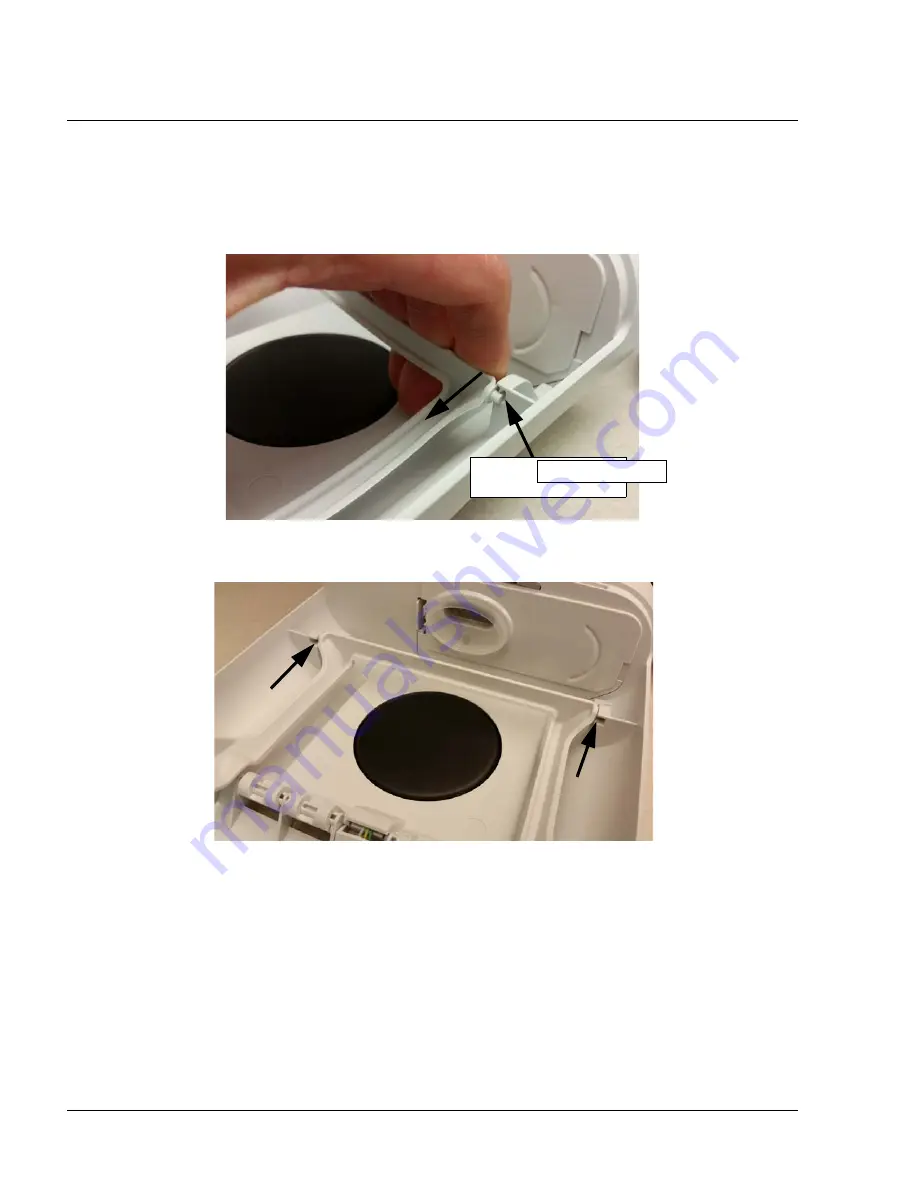
Pull back one of the other ends of the Lifting Tray and align into the groove (refer to illustration
below.).
4.
Repeat on other side.
F
IGURE
7-17: L
IFTING
T
RAY
I
NSTALLATION
F
IGURE
7-18: L
IFTING
T
RAY
I
NSTALLED
Pull back Tray and
align into groove
Heat Shield
Summary of Contents for DreamStation
Page 1: ...DreamStation Service Technical Reference Manual ...
Page 5: ...1117539 VER 07 This page intentionally blank ...
Page 6: ...PAGE 1 1 1117539 VER 07 2016 Koninklijke Philips N V All rights reserved ...
Page 11: ...PAGE 1 6 1117539 VER 07 This page intentionally blank ...
Page 13: ...PAGE 2 2 1117539 VER 07 This page intentionally blank ...
Page 15: ...PAGE 3 2 1117539 VER 07 This page intentionally blank ...
Page 134: ...PAGE 8 8 1117539 VER 07 This page intentionally blank ...
Page 135: ...NO 1117539 VER 07 EMH 06 04 2016 ...


