


RESOLUTE FS with
BiSS
®
Safety
encoder system installation guide and safety manual
15
Original
instructions
REXA ring installation
REXA should be flange mounted onto a flat surface, this
eliminates all installation errors except eccentricity, which
can be compensated using twin readheads.
Although taper mounting is best for thin cross-section
rings, it is not suitable for thick cross-section
REXA rings.
The REXA ring should be flange mounted onto a
flat surface to minimise 2-per-rev distortion.
Some eccentricity of the ring is acceptable because it
will be compensated by the use of twin readheads.
To avoid distorting the scale, the REXA should not be
interference fitted.
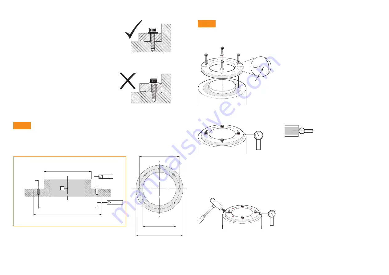
Mounting shaft preparation
There is a mounting face on the lower side of the
REXA ring. A flat surface should be prepared on the
mounting shaft to match. The total axial run-out of the
mounting surface should be better than 10 µm.
A
A
A
(<
D1 - 0.75)
D4
D2
0.01
Ø 0.2
For dimensions D1, D2, D3, D4 and number of holes N,
please refer to ring drawing.
D4
D1
D3
Step 2
Mounting method
Dimple or slot
indicates
fiducial mark
DO NOT INTERFERENCE FIT
N × M5 × 0.8
× 10 deep
Remove the protective film from the surface of the REXA.
Clean the mounting face on the lower side of the REXA.
Clean the mating surface on the mounting shaft.
Place the REXA onto the mounting shaft, then insert
four off M5 screws with flat washers into the four screw
holes by the fiducial marks. DO NOT tighten the screws
at this point – simply engage the threads ensuring that
the heads do not touch the ring.
NOTES:
Do not lubricate the screws
Do not use a thread locking compound
Recommended screw type is M5 x 0.8 and
must comply with: ISO 4762/DIN 912 grade
10.9 minimum/ANSI B18.3.1M.
Minimum thread engagement is 10 mm.
Set up a Dial Test Indicator (DTI) to measure the
run-out on the REXA ring.
NOTE:
Use a DTI with low contact force to avoid
scratching the scale surface.
A DTI with a ruby ball stylus is recommended as a
further precaution against scratches.
Rotate the ring through 360° making a note of the high
and low readings.
NOTE:
At this stage the ring is not firmly fixed, so to
avoid causing the ring to shift position, rotate the ring
slowly and smoothly.
Where the DTI shows the lowest radius reading, gently
tap the opposite side of the ring on the edge using a
rubber mallet, until the DTI reading is approximately at
the ‘mid point’ of the run-out.
Now find the new lowest radius reading and again tap
the opposite side of the ring with a rubber mallet until
the DTI reading is at the ‘mid point’ of the run-out.
Continue this process until the run-out of the ring is
approximately 30 µm (0.0012 inches). This is the initial
adjustment. Now adjust to 10 µm at the fiducial points.
Step 1