


RESOLUTE FS with
BiSS
®
Safety
encoder system installation guide and safety manual
12
Original
instructions
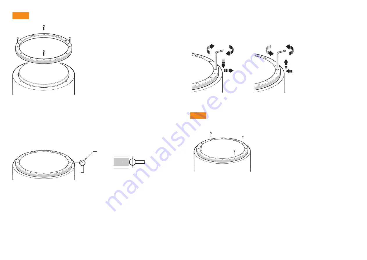
Step 2
DTI
Use a non-contact or low force < 0.04N DTI with
ruby ball to ensure scale surface is not marked.
Adjust the screws to reduce the range of radial displacement. When adjusting, identify the screw
location with the lowest radial displacement and tighten that screw, aiming for the average of the
highest and lowest indicator readings.
Repeat this process until the DTI readings are within ±5 μm at the screw locations.
NOTE:
It may be necessary to loosen screws whilst tightening other screws.
NOTE:
At this stage, the screws
should only be lightly tightened
(less than 0.5 Nm)
to allow further final adjustment.
Remove the protective film from the surface of the RESA.
Clean shaft taper and internal taper of RESA as
recommended in the storage and handling section.
Insert the first screws:
For RESA rings with 6, 9 or 18 mounting holes,
use 3 equally spaced M3 screws.
For RESA rings with 6, 9 or 18 mounting holes,
use 3 equally spaced M3 screws.
For RESA rings with 12, 16 or 20 mounting holes,
use 4 equally spaced M3 screws.
NOTES:
Do not lubricate the screws
Do not use a locking compound
Recommended screw type is M3 × 0.5 and must
comply with: ISO 4762/DIN 912 grade 10.9
minimum/ANSI
B18.3.1M.
Minimum thread engagement is 6 mm.
Insert the screws so that the RESA is loosely
connected to the shaft, then roughly align the ring by
eye and touch.
Lightly tighten the screws. Use a Dial Test Indicator
(DTI) to check the radial displacement at the screw
locations.
NOTE:
Disregard the radial displacement between the
screw locations.
Step 3
Insert the next screws:
For RESA rings with 6, 9 or 12 mounting holes,
insert all the remaining M3 screws.
For RESA rings with 16 mounting holes,
insert 4 equally spaced M3 screws.
For RESA rings with 18 mounting holes,
insert 6 equally spaced M3 screws.
For RESA rings with 20 mounting holes,
insert 8 equally spaced M3 screws (in four groups
of two) between existing screws.
As described in step 2, adjust all the screws inserted
thus far, so that the radial displacement at each screw
location is within ±5 µm.
Again, at this stage, the screws should only be lightly
tightened (less than 0.5 Nm).
NOTE:
You may notice that the torque required to
achieve the radial displacement tolerance will be slightly
higher during step 3 than during step 2. This is normal.