SRP - User manual
Ref.: RX182/006
Version 01/2017 - English
This document must not be reproduced nor information therein disclosed without our authorization
Page 20 / 28
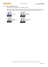
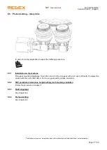
7.4 Proper tooth meshing validation
Checking that both pinions are properly meshing with the rack by measuring the clearance between rack
and pinion teeth (t
b2
)
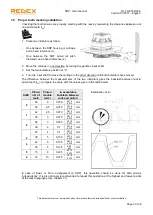
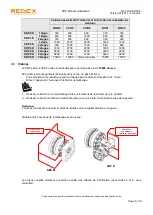
1. Place two indicators as follow:
-
One between the SRP housing or carriage
and a fixed reference (1).
-
One between the SRP pinion (at pitch
diameter) and a fixed reference (2).
2. Move the carriage in one direction by turning the gearbox input shaft.
3.
Set the two indicators position at “0”.
4. Turn the input shaft to move the carriage in the other direction until both indicators have moved.
The difference between the measurements of the two indicators gives the backlash between rack &
pinion teeth (t
b2
). Compare the value with the values given in the table below.
SIZE
Pinion
nbr of
teeth
Pinion
module
(mm)
t
b2
acceptable
backlash between
rack and pinion
0
45
2
0,050
0,015
mm
-0,015
36
2,5
0,070
0,015
mm
-0,015
1
42
2,5
0,070
0,015
mm
-0,015
35
3
0,070
0,015
mm
-0,015
2
52
3
0,070
0,015
mm
-0,015
39
4
0,1
0,015
mm
-0,015
3
45
4
0,1
0,015
mm
-0,015
36
5
0,135
0,035
mm
-0,035
4
42
5
0,135
0,035
mm
-0,035
35
6
0,135
0,05
mm
-0,05
5
15
8
0,205
0,070
mm
-0,070
6
14
10
0,275
0,070
mm
-0,070
In case of Dual- or Twin- arrangement (2 SRP), this operation should be done for both pinions
independently. It is also strongly recommended to repeat this operation at the highest and lowest points
of the rack topography (see chapter 7.1).
Explanation of t
b2
:


