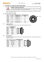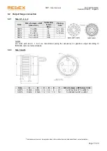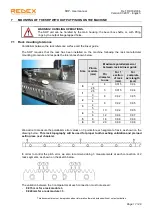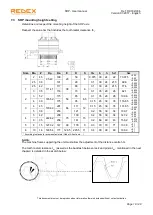
SRP - User manual
Ref.: RX182/006
Version 01/2017 - English
This document must not be reproduced nor information therein disclosed without our authorization
Page 12 / 28
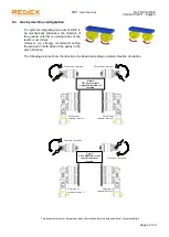
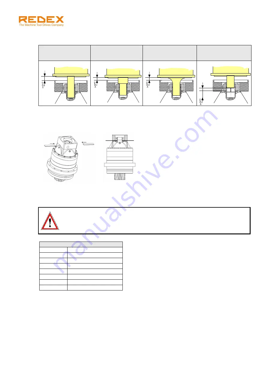
3. Check that the motor / gearbox interface dimensions are correct. Avoid the following improper
assemblies:
Motor shaft should
not reach the end of
the input bore.
Motor shoulder must
not reach the
clamping hub.
Motor radius must not
reach the clamping
hub.
Motor shaft must be
locked on the full
clamping hub width.
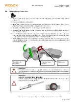
4. Make sure that the clamping screws of the input split-bore are not tight.
5. For size 6 only, install the 2 keys into the appropriate grooves to prevent the input bore from moving
down while mounting the motor. See pictures:
6. Lower the motor
vertically
onto the gearbox (and for size 6: maintain the 2 additional keys in
position) and fix it by tightening the 4 screws of the flange at the adequate tightening torque (table
below):
WARNING!
The motor must be mounted without applying any stress on the input shaft. The motor
centering is done by the gearbox input shaft. That is why it is absolutely necessary to mount
the motor vertically. A wrong mounting can lead to bad running conditions damageable for
the gearbox.
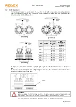
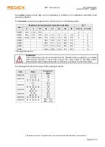
7. Gradually tighten the 2 clamping hub screws by half rotations until the tightening torque shown in the
table below is reached.
Screws of the motor flange
Screw type
Tightening torque (Nm)
M6
10
M8
25
M10
49
M12
86
M14
135
M16
210
M18
290


