SRP - User manual
Ref.: RX182/006
Version 01/2017 - English
This document must not be reproduced nor information therein disclosed without our authorization
Page 17 / 28
7
MOUNTING OF THE SRP WITH OUTPUT PINION ON THE MACHINE
WARNING! HANDLING OPERATIONS.
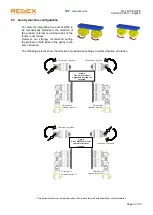
The SRP unit can be handled by the main housing, the bevel box shafts, or, with lifting
rings by the output flange tapped holes.
7.1 Rack mounting tolerance
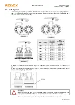
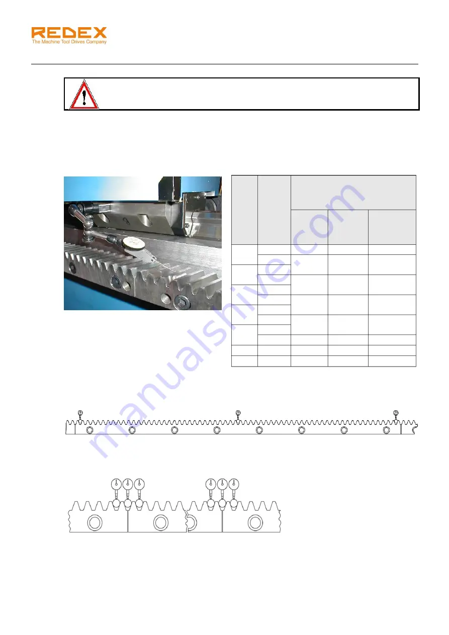
Parallelism between the rack reference surface and the linear guide
The SRP requires that the rack has been installed on the machine following the rack manufacturer
mounting procedure and respects the tolerances shown below:
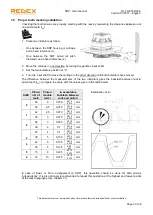
We advice to measure the parallelism error values on 3 points for each segment of rack, as shown on the
drawing below.
This rack topography will be used for proper tooth meshing validation and preload
setting (see next chapters).
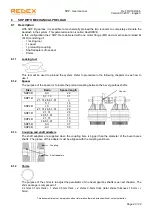
In order to control the pitch error, we also recommend doing 3 measurements at each connection of 2
rack segments, as shown on the sketch below.
The variation between the 3 comparators at each connection must not exceed:
-
0.015 mm for a rack module 3,
-
0.020mm for a rack module > 3.
Size
Pinion
module
(mm)
Maximum parallelism error
between rack & linear guide
Pin
diameter
to use
For 1
section
of rack
(mm)
For
complete
axis length
(mm)
0
2
4
0,015
0,04
2,5
5
0,015
0,04
1
2,5
3
6
0,02
0,05
2
3
4
8
0,02
0,05
3
4
5
10
0,02
0,05
4
5
6
12
0,04
0,07
5
8
16
0,06
0,08
6
10
20
0,06
0,08


