background image

RED DSMC OPERATION GUIDE

COPYRIGHT © 2014 RED.COM, INC  

 955-0020_V5.2, REV-G  |   39

REPLACE THE HOOD SCOOP

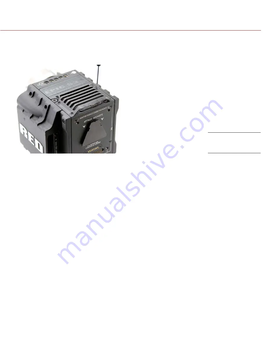
The hood scoop on some EPIC-X and EPIC-M models extends beyond the rear plane of the BRAIN. RED offers 

shorter hood scoops so that you can attach an LCD or other accessory to the mounting locations on the top 

of the +1 Adaptor Module. 

To replace DSMC fan hood scoop, follow the instructions below:.
1.  Turn off the BRAIN.
2.  Use a T8 Torx driver to remove the four (4) M3x0.5 x 6 mm cap screws holding the hood scoop.
3.  Lift off the hood scoop.
4.  Position the replacement hood scoop on the BRAIN. 
5.  Align the hood scoop screw holes with the threaded holes on top of the BRAIN.
6.  Use a T8 Torx driver to tighten four (4) M3x0.5 x 6 mm cap screws in a cross pattern (“X” pattern). DO NOT 

FULLY TIGHTEN.

7.  Tighten the four (4) M3x0.5 x 6 mm cap screws evenly in a cross pattern (“X” pattern). DO NOT exceed 30 

in-oz, or damage may occur.

Replace the Hood 

Scoop

Summary of Contents for DSMC DRAGON

Page 1: ...EPIC SCARLET V5 2 DRAGON MYSTERIUM X RED COM RED DSMC O PERAT ION GU IDE...

Page 2: ...Menu 123 Chapter 6 Record and Monitor Audio 126 Overview 126 Audio Data Path 126 Set Up Audio 127 Audio Input Source Options 127 Audio Output Options 130 Audio Meter VU Meter 131 Audio During Playback...

Page 3: ...from the use of any technical or operational information contained in this document For comments or questions about content in this Operation Guide please send a detailed e mail to OpsGuides red com...

Page 4: ...n interfer ence to radio and TV reception The user is cautioned that changes and modifications made to the equipment without the approval of manufacturer could void the users authority to operate this...

Page 5: ...negative effects on human health and the environment which could otherwise arise from inappropriate waste handling Please contact your local authority for further details of your nearest designated c...

Page 6: ...ge 0 C to 40 C 32 F to 104 F Storage range 20 C to 50 C 4 F to 122 F If there are any performance issues with your camera or acces sories when operating within this temperature range please file a sup...

Page 7: ...ge to the battery DO NOT connect the positive and negative terminals to a metal object such as a wire DO NOT transport or store the battery together with metal ob jects such as jewelry hairpins etc as...

Page 8: ...EPIC M RED DRAGON EPIC X RED DRAGON SCARLET DRAGON MYSTERIUM X EPIC M MYSTERIUM X EPIC X MYSTERIUM X SCARLET X MYSTERIUM X MONOCHROME EPIC M MONOCHROME EPIC X MONOCHROME RED DRAGON MONOCHROME EPIC M...

Page 9: ...ture advanced image processing capabilities and integrated audio system the EPIC delivers a remarkable amount of technology packed into a five 5 lb body EPIC M RED DRAGON CARBON FIBER The EPIC M RED D...

Page 10: ...itude and image density The RED DRAGON sensor is a model for image innovation leading the way in the evolution of digital cinema technology Boasting an industry leading 19 megapixels at 6K resolution...

Page 11: ...al image received from the sensor is formatted as a pixel defect corrected but in all other aspects unprocessed 16 bit per pixel RAW data frame Each RAW frame or sequence of RAW frames in a clip is co...

Page 12: ...C is ideally suited to capture video and still images simultaneously Using REDCINE X PRO or other editing applications supporting the RED SDK you can pull full resolution still images from R3D files P...

Page 13: ...tion For example ask someone to swing their arm What you would observe in a traditional recording of this action is constant motion blur until the arm stops However what your eye sees is both motion b...

Page 14: ...e OLPFs on page 30 Rails Mounts Tactical Gear and Cables on page 30 WARNING Modules displays and accessories are NOT HOT SWAPPABLE meaning that you cannot remove or install the item while the camera i...

Page 15: ...ions for all BRAINs LED COLOR FLASHING DESCRIPTION Power Status LED PWR Off No power present Green Power present camera on Red flashing Power present 5 min of battery time left Red Power present camer...

Page 16: ...carbon fiber BRAIN DSMC SIDE SSD MODULES DSMC media modules attach to the DSMC to enable the use of RED MINI MAG or REDMAG 1 8 SSD media Both DSMC side SSD module systems have the same EVF LCD LEMO c...

Page 17: ...y 2 Programmable key User Key 1 2 Press Eject Media REC button Programmable key Full Press Record Toggle Half Press AF Start REAR SSD MODULE The Rear SSD Module secures to the back of a Module Adaptor...

Page 18: ...RED STATION RED MINI MAG 750 0055 REDMAG 1 8 SSD 48GB 750 0044 REDMAG 1 8 SSD 64GB 750 0025 REDMAG 1 8 SSD 128GB 1 750 0021 REDMAG 1 8 SSD 240GB 2 750 0061 REDMAG 1 8 SSD 256GB 1 750 0026 REDMAG 1 8 S...

Page 19: ...g points on top for configuration support Most DSMC modules require a Module Adaptor or 1 Adaptor Module to attach to your BRAIN For more information go to Configure Your DSMC on page 33 WARNING The M...

Page 20: ...if a Pro I O Module is connected to the BRAIN NOTE The default auxiliary power output setting is on To toggle the power setting on off go to Menu Power Power Out 1 PWR The last power output setting i...

Page 21: ...SMC AC Power Adaptor or DSMC Side Handle you can hot swap batteries without interrupting recording RED offers the following DSMC power modules ITEM PART NUMBER Pro Battery Module Dual 720 0005 Pro Bat...

Page 22: ...long term mobile power and attach to the BRAIN via a DSMC power module or other RED accessory such as the DSMC Side Handle RED chargers replenish lost capacity for REDVOLT REDVOLT XL and RED BRICK bat...

Page 23: ...nnections in one 1 module providing a central hub for professional audio and video components The Pro I O Module offers the following features Centralized ports that make it easy to manage connections...

Page 24: ...e with both EPIC DRAGON and SCARLET DRAGON cameras the 4K Broadcast Module uses four 4 3G SDI output connections to broadcast 4K video at up to 60 frames per second Five 5 1 4 20 mounting holes are bu...

Page 25: ...tor viewing options RED touchscreen displays enable you to use gestures to navigate menus and adjust camera parameters RED displays feature 8 bit RGB 4 4 4 progressive scan providing up to 16 7 millio...

Page 26: ...wide x 1024 high full color 10 000 1 typical 2 0 to 5 0 1 DSMC REMOTES AND CONTROLS This section describes the DSMC remotes and controls The DSMC Side Handle REDMOTE and REDLINK Bridge provide a wide...

Page 27: ...f DSMC Side Handle user keys and default actions go to Default Key Functions on page 191 RED SWITCHBLADE M The RED Switchblade M is a low profile and lightweight interface solution that mounts to the...

Page 28: ...EDMOTE Operation on page 133 IMPORTANT To operate properly upgrade both REDMOTE and DSMC firmware to the most recent version REDLINK BRIDGE The REDLINK Bridge is a wireless module that provides commun...

Page 29: ...i PL Mount 725 0003 DSMC Al Canon Mount 725 0004 DSMC Ti Canon Mount 725 0005 DSMC Al Nikon Mount 725 0006 DSMC Ti Nikon Mount 725 0007 DSMC Al Leica M Mount 725 0008 DSMC Motion Mount Ti PL1 725 0012...

Page 30: ...vironment For more information go to Use a Tripod or Monopod on page 40 RED offers the following modular DSMC Interchangeable OLPFs ITEM PART NUMBER DSMC Skin Tone Highlight OLPF 790 0461 DSMC Low Lig...

Page 31: ...camera Failure to do so may result in damage to the item or DSMC that will not be covered under warranty POWER INPUTS 1 2 There are two 2 primary power inputs that provide power to the DSMC BRAIN DSMC...

Page 32: ...OWER The DSMC accepts input voltages of 11 5 V to 17 V DC and can draw a maximum current of 12 A The BRAIN can be powered continuously by connecting one 1 of the following to the DC IN port on the BRA...

Page 33: ...side plate was installed 5 Press the DSMC Side Handle down flush along the side of the BRAIN 6 Rotate the thumbscrew upward while applying steady pressure until tight REMOVE THE DSMC SIDE HANDLE WARN...

Page 34: ...plate 4 Insert the lip on the RED Switchblade M into the slot where the lip of the BRAIN side plate was installed 5 Press the Switchblade M down flush along the side of BRAIN 6 Tighten the thumbscrew...

Page 35: ...rx driver 1 Turn off the BRAIN 2 Remove the REDMOTE if attached 3 Position the Module Adaptor over the V mount on the rear of the BRAIN 4 Apply pressure and tighten the four 4 captive screws in a cros...

Page 36: ...Torx driver to loosen the screws attaching the Module Adaptor to the BRAIN 3 Remove the Module Adaptor from the BRAIN INSTALL THE 1 ADAPTOR MODULE REQUIRED TOOL T20 Torx driver 1 Turn off the BRAIN 2...

Page 37: ...T20 Torx driver DO NOT FULLY TIGHTEN 6 Fully tighten the four 4 screws in a cross pattern X pattern DO NOT OVERTIGHTEN REMOVE THE 1 ADAPTOR MODULE REQUIRED TOOL T20 Torx driver 1 Turn off the BRAIN 2...

Page 38: ...ith the rear of the adaptor module 4 Apply pressure and use a T20 Torx driver to turn the lock on the bottom of the adaptor module clockwise into the Lock position REMOVE A DSMC MODULE REQUIRED TOOL T...

Page 39: ...ollow the instructions below 1 Turn off the BRAIN 2 Use a T8 Torx driver to remove the four 4 M3x0 5 x 6 mm cap screws holding the hood scoop 3 Lift off the hood scoop 4 Position the replacement hood...

Page 40: ...eight of your DSMC configuration RED is not responsible for any damage caused by using a tripod monopod mount or support system that does not provide sufficient support WARNING DO NOT use excessive fo...

Page 41: ...or most HDTVs VIDEO MONITOR CATEGORIES Video monitor outputs are separated into three 3 categories VIEWFINDER The Upper Status Row Live Action Area and Lower Status Row display Default output is the...

Page 42: ...convenient access to menus overlays and other critical camera information Functionality varies based on monitor output type and firmware version 1 2 3 The DSMC GUI menu is separated into three 3 main...

Page 43: ...M DESCRIPTION FOR MORE INFORMATION GO TO 1 Frame Rate FPS Sensor frame rate Frame Rate on page 71 2 ISO Camera sensitivity ISO Native on page 70 3 F Stop Aperture Lens F Stop information F Stop T Stop...

Page 44: ...r Status Row item except for REDCODE you can select the Advanced button to access the related menu in the Advanced Menus For example select Advanced in the Frame Rate menu to open Menu Settings Projec...

Page 45: ...T LIST Select the Edit List button in the Upper Status Row menus to change the values that display for each setting For example if you open the Frame Rate menu and select Edit List the camera lets you...

Page 46: ...op menu is visible when a DSMC Nikon Mount DSMC Canon Mount or DSMC Canon Motion Mount is installed and a supported lens is attached This enables you to adjust the aperture F stop of the attached lens...

Page 47: ...or projection area Guides on page 68 5 Clip Filename Filename of the clip being recorded or filename of the next clip to be recorded DSMC Media Operation Guide 6 Timecode Value Current timecode value...

Page 48: ...agement on page 95 Sensor Calibration on page 98 Cal T E CAL T E Indicator on page 49 HDR Displays when HDRx mode is on HDR Menu on page 114 False Color Mode Displays modes False Color Modes on page 5...

Page 49: ...he total image are at an exposure level that is at risk of displaying noise when pushed to higher ISO or FLUT values in post production SYSTEM STATUS INDICATORS This section describes the colors and b...

Page 50: ...Timecode Genlock Multi Camera Setup on page 143 LAN INDICATOR The LAN indicator shows the current status of an external LAN connection through the Gig E port Gray External control of the camera is no...

Page 51: ...ouchscreen by using the following gestures Tap Tap has many functions Tap to select a Basic Menu submenu or button If a menu is open tap anywhere outside the menu to save any changes and close the men...

Page 52: ...ess ENTER to confirm a setting or access the selected menu Navigate the menus using a DSMC Side Handle RED Switchblade M or REDMOTE using the following controls Press ENTER to open the menu then rotat...

Page 53: ...igation Group Navigate menus and menu items go to Navigation Group on page 52 7 User Keys A D A Cycle Auto Focus Mode B Auto White Balance C Toggle 1 1 Magnify on off D Toggle Exposure Mode on off 8 U...

Page 54: ...ance Color temperature 3 Frame Rate Current frame capture rate 4 Resolution Recording resolution 5 ISO Camera sensor sensitivity 6 Temperature Displays camera sensor and core temperature respectively...

Page 55: ...ertent menu changes NOTE RED Switchblade M keys are user programmable For more information go to Key Mapping on page 89 OPERATION MODES The RED Switchblade M OLED display reflects the currently select...

Page 56: ...ture when a supported Canon Nikon or Cooke lens is attached 3 White Balance Color temperature 4 REDCODE REDCODE compression setting 5 Media Status Displays media location and remaining media capacity...

Page 57: ...yback Menu on page 110 Power Power sources settings status and shutdown Power Menu on page 113 HDR HDRx mode and settings HDR Menu on page 114 Focus Focus modes features settings and rack focus Focus...

Page 58: ...s False Color Zebra Tools article available at www red com learn red 101 exposure false color zebra tools FALSE COLOR MODES False color modes include None Exposure Focus Video and Edge NOTE Only monit...

Page 59: ...image content making it easier to judge focus Adjust zoom and focus to easily see which objects are coming into focus When enabled the F indicator displays in the Lower Status Row VIDEO Displays a co...

Page 60: ...on of the horizon The Horizon overlay consists of two 2 short side bars that are always horizontally centered on the monitor and a single longer horizon line that adjusts to the horizon based on the o...

Page 61: ...p of the menu The other settings on the menu are applicable to the selected monitor NOTE Changes to Monitor Control settings take effect when you close the menu MODE Determines the elements displayed...

Page 62: ...nd HDMI Out on page 176 FREQUENCY Determines the monitor frequency Available frequencies depend on the selected monitor For HD SDI monitors the frequency depends on the project time base For more info...

Page 63: ...the video is scaled so that the menus are not overlaid on the video When this option is enabled the video is not scaled This options lets creates a control surface on a monitor without to scaling the...

Page 64: ...a template in the Overlay Editor Edit Edit the selected camera overlay in the Overlay Editor Delete Delete the selected camera overlay EXPORT AND IMPORT OVERLAYS Export selected overlay from camera to...

Page 65: ...t moves to the new position PRIORITY The camera can only have one 1 control monitor for interacting with camera settings The Priority tab determines the order in which a monitor becomes the control mo...

Page 66: ...ideo area on the LCD to toggle record Double Tap Left 25 to Start AF Double tap the left 25 of the video area on the LCD to start autofocus when compatible lenses are used For a list of compatible len...

Page 67: ...re time changes REMAINING POWER Current Batt Displays the remaining percentage of active battery Default Total Time Displays the total run time left of battery power taking into account all available...

Page 68: ...on the main screen when rack focus is enabled For more information go to Set Up Rack Focus on page 118 Off Does not displays the focus distance of rack points when rack focus is enabled Default GUIDES...

Page 69: ...e Guide instead of the record format NOTE The Relative to Frame Guide check box is available on the Action Guide and Title Guide tabs GENERAL TAB Enable Disable and select the location Relative To col...

Page 70: ...50 to 12 800 Default is ISO 800 RED DRAGON Range is ISO 250 to 12 800 Default is ISO 800 MONOCHROME and RED DRAGON MONOCHROME Range is ISO 250 to 12 800 Default is ISO 2000 For more information see th...

Page 71: ...a default of 0 000 NOTE Selecting Auto White Balance calculates a new Tint value The value doesn t change if you adjust the color temperature manually Selecting a preset resets Tint to 0 000 PRESETS...

Page 72: ...e rate at which the footage will be played back The project time base displays in the lower left corner of the display The following project time bases are available 23 98 FPS default 24 00 FPS 25 00...

Page 73: ...40 6K HD 83 542 3 5K 3 2 116 75 6K 6 5 82 91 3 5K 4 3 103 85 6K 4 1 169 34 3 5K 5 4 97 394 6K 8 1 334 81 3 5K 4 1 289 18 5 5K FF 88 845 3 5K 8 1 400 00 5 5K 2 1 92 989 3K FF 160 65 5 5K WS 110 11 3K...

Page 74: ...5 0020_V5 2 REV G 74 FORMAT MAX FRAME RATE FPS FORMAT MAX FRAME RATE FPS 4K 6 5 121 05 2K 6 5 240 55 4K 3 2 102 24 2K 3 2 203 37 4K 4 3 90 932 2K 4 3 180 99 4K 5 4 85 27 2K 5 4 169 78 4K 4 1 253 52 2K...

Page 75: ...e is always 1 FPS NOTE Frame rates below are based on a 23 98 time base 8 1 compression with Lookaround disabled FORMAT MAX FRAME RATE FPS 6K FF 12 08 in Burst mode 5K FF 24 62 5K 2 1 25 95 5K WS 30 7...

Page 76: ...ce the maximum frame rate for each anamorphic format and the corresponding non anamorphic format is the same NOTE Frame rates below are based on a 23 98 time base 8 1 compression with Lookaround disab...

Page 77: ...sure possible for the frame rate For more information go to Speed Ramp Mode on page 87 EXPOSURE SHUTTER SPEED Enter the exposure value as a shutter speed 1 xx sec MYSTERIUM X Slowest speed is 1 sensor...

Page 78: ...ce connected to the timecode connector on the BRAIN External Rear Module Varies by device Uses the timecode from an external device connected to a Pro I O Module or a 4K Broadcast Module SLATE Use the...

Page 79: ...a 2 40 1 aspect ratio RESOLUTION DESCRIPTION DIMENSIONS PIXELS WIDTH HEIGHT 6K FF 6K RAW Full Frame 6144 3160 6K 2 1 6K RAW 2 1 6144 3072 6K WS 6K RAW Wide Screen 2 4 1 6144 2592 6K HD 6K RAW HD 16 9...

Page 80: ...1 3 5K RAW 2 1 3584 1792 3 5K WS 3 5K RAW Wide Screen 2 4 1 3584 1512 3 5K HD 3 5K RAW HD 16 9 3456 1944 3 5K 3 2 3 5K RAW 3 2 3360 2240 3 5K 4 3 3 5K RAW 4 3 3360 2520 3 5K 5 4 3 5K RAW 5 4 3360 268...

Page 81: ...W 5 4 2400 1920 2 5K 4 1 2 5K RAW 4 1 2560 640 2 5K 8 1 2 5K RAW 8 1 2560 320 2K FF 2K RAW Full Frame 2048 1080 2K 2 1 2K RAW 2 1 2048 1024 2K WS 2K RAW Wide Screen 2 4 1 2048 864 2K HD 2K RAW HD 16 9...

Page 82: ...RAW Full Frame 5120 2700 5K 2 1 5K RAW 2 1 5120 2560 5K WS 5K RAW Wide Screen 2 4 1 5120 2160 5K HD 5K RAW HD 16 9 4800 2700 5K 6 5 5K RAW 6 5 3240 2700 4K 4K RAW Full Frame 4096 2160 4K 2 1 4K RAW 2...

Page 83: ...16 9 4800 2700 25 92 14 58 29 74 5K 1 22 1 5K RAW 1 22 1 3300 2700 17 80 14 58 23 01 4K FF 4K RAW Full Frame 4096 2160 22 12 11 66 25 01 4K WS 4K RAW Wide Screen 2 4 1 4096 1708 22 12 9 22 23 96 4K H...

Page 84: ...and 2x with each format SCARLET DRAGON Supports anamorphic 2x for 5K 6 5 EPIC MYSTERIUM X and SCARLET MYSTERIUM X Supports the following 5K FF Anamorphic 1 3x and 2x 5K 1 22 1 Anamorphic 2x NOTE To se...

Page 85: ...Frame Guide and recording area are scaled down on the display so that you can see what images will enter the recording area To assign a Shading overlay to the Lookaround area the area outside of the...

Page 86: ...e the camera records the specified number of frames for each external trigger This mode limits the REDCODE based on sustainable record rates To use Frame Trigger mode follow the instructions below 1 G...

Page 87: ...de drop down menu 3 Use the Limit Recording to fields to set the recording to end at a predefined frame limit optional 4 Select a ramp target Ramp A B C D Each ramp target is tied to a specific Target...

Page 88: ...th the exposure and frame processing settings to achieve the effect you want NO FRAME PROCESSING Normal frame processing mode The Frames to Process selection does not affect recording FRAME SUMMING Fr...

Page 89: ...r specific situations map Pre Record to a key Menu Settings Setup Keys Record Start Pre Record For more information go to Keys on page 89 INDICATOR Enable Sounds Select this check box to enable sounds...

Page 90: ...map any key even if the key is not currently accessible For example you can map the REDMOTE keys even if a REDMOTE is not present WARNING It is possible to remap the navigation keys using this tab Ho...

Page 91: ...Specify which devices the camera can send commands to All The camera can send commands to all devices on the network None The camera can only receive commands The camera cannot send commands Custom Th...

Page 92: ...ets the property on other cameras If this camera receives a SET command the camera does not send the command to other cameras devices Enable External Control This camera can be controlled via TCP IP f...

Page 93: ...for devices connected to the SYNC connector on the BRAIN Sync In The camera input is used as a sync in signal for MoCo General Purpose In Use the Brain GPI In High Low drop down menus to map inputs t...

Page 94: ...In practice Low High correlate to the press release of a trigger or the on off position of a switch Low The falling edge transition from high voltage to low voltage High The rising edge transition fr...

Page 95: ...ecord Toggle 5 NOTE For more information about the Pro I O Module see the Pro I O Module Operation Guide available at www red com downloads FAN AND TEMPERATURE MANAGEMENT The DSMC is controlled by com...

Page 96: ...d SCARLET DRAGON Target temperature range is 55 C to 70 C A target temperature of 65 C works best across most environmental conditions EPIC MYSTERIUM X and SCARLET MYSTERIUM X Target temperature range...

Page 97: ...rmation see the DSMC Motion Mount Operation Guide available at www red com downloads MOTOR CONTROL Use the Motor Control menu to set up the RED 3 Axis Lens Control System For more information see the...

Page 98: ...andom with no fixed patterns or lines The sensor is calibrated The noise has patterns or lines Calibrate the sensor For more information go to Calibration Capture Black Shading on page 98 WHEN TO CALI...

Page 99: ...for the current in camera user created calibration map Save To Media The calibration map created by black shading will be saved to an SSD Leave both Save check boxes deselected The calibration will o...

Page 100: ...n To save a calibration map to your hard drive copy the entire sub folder for example 48_32C_20140128122150 to your drive CALIBRATION MANAGEMENT Use the Calibration Management menu to apply import and...

Page 101: ...core temperature to reach maximum operating temperature 5 Once the camera core is at maximum operating temperature select High Temperature Calibration LENS CALIBRATION There are a quantity of electro...

Page 102: ...ens calibration file 1 Attach a DSMC Canon Mount or DSMC Nikon Mount to the BRAIN 2 Attach an electronic lens 3 Manually set the first focal length you want to calibrate 4 There are two 2 ways to star...

Page 103: ...displays Once the calibration process starts DO NOT touch the lens as doing so may cause the lens to calibrate incorrectly 5 Select OK after the calibration file is created 6 To calibrate the next fo...

Page 104: ...at has already been calibrated the new files overrides the previ ous file The lens calibration process for the current focal length starts and a progress bar displays Once the calibration process star...

Page 105: ...calibration file name in the Camera list and select Edit The following information displays Mount Type Focal Length F Stop Range Overall F stop range of lens Lens Status Calibrated Focal Lengths 3 You...

Page 106: ...ected file from camera to SSD All Export all files from camera to SSD Import selected file from SSD to camera All Import all files from SSD to camera LENS CALIBRATION ACTIONS Edit View and edit the se...

Page 107: ...on the touchscreen 3 Touch each box with your finger Each green box turns blue 4 To exit the self test perform one 1 of the following actions Touch all of the boxes so that they are all blue Press an...

Page 108: ...ot detected by the BRAIN Attached The module is attached and detected CAMERA INFO Displays the following camera information Model Camera type EPIC or SCARLET and sensor type Version Current firmware v...

Page 109: ...and control of each shooting environment The camera checks the OLPF type and adjusts the color scienced based on the selected OLPF CHECK INSTALLED OLPF To see which OLPF is installed follow the instru...

Page 110: ...form the following actions Move selected clip to the Play List All Move all clips to the Play List Apply Image Metadata Image data such as color gain and curves recorded with the image displays with t...

Page 111: ...N GUIDE COPYRIGHT 2014 RED COM INC 955 0020_V5 2 REV G 111 PLAYBACK CONTROLS The images below show the Playback controls 1 3 2 4 5 6 7 8 9 14 20 10 11 12 13 15 16 18 19 17 Playback Controls Play Optio...

Page 112: ...ck Menu Media and move clips to the Play List field 13 Playback Speed Option to select x1 x2 x4 x8 or x16 playback speed 14 Marker Options Displays the following subset of options In Point Remove In O...

Page 113: ...ort is functional FAULT A short or overcurrent tripped the electronic fuse Remove the device that is connected to the module as it may be drawing too much power Select RESET to clear the fault POWER S...

Page 114: ...ed and the HDR indicator in the Lower Status Row is gray To enable HDRx follow the instructions below 1 Go to Menu HDR 2 Select HDRx The HDR text in the Lower Status Row turns white 3 Select the numbe...

Page 115: ...menu has additional options DSMC Nikon Mount and a supported lens is attached The lens focus switch is set to A or M A DSMC Canon Mount and a supported lens is attached The lens focus switch is set t...

Page 116: ...rk or distant Inadequate contrast between the subject and background Scene has reflective highlights Subject is backlit Inadequate surface contrast detail inside the window NOTE Use Edge mode for assi...

Page 117: ...Spot from the Zone drop down menu select a size from the Size drop down menu 5 Select the Enhanced A F check box 6 Select the monitor dedicated to using the Enhanced A F feature from the Monitor drop...

Page 118: ...CUS Use the Rack tab to configure up to four 4 focus points and execute rack focus between them SET UP RACK FOCUS 1 Ensure that a DSMC Nikon Mount DSMC Canon Mount or DSMC Canon Motion Mount is instal...

Page 119: ...h the lens moves Move the slider to the left for a slower speed and to the right for a faster speed 7 Select the number of rack points 1 4 from the Rack Points drop down menu A line for each rack poin...

Page 120: ...NOTE To view the focus distance for each rack point on the main screen go to Menu Settings Display Modes and enable Rack Target Distance mode For more information go to Lens Tab on page 68 10 Select a...

Page 121: ...igger the exposure calculation CONTINUOUS IN PREVIEW When in Continuous in Preview mode the camera continuously adjusts F stop and exposure to meet the user selected brightness The auto exposure adjus...

Page 122: ...2 8 and f 5 6 If Free Value Selection is enabled the algorithm only selects F stop parameters between f 2 8 and f 5 6 This setting limits the range of focal depth AE LOCKS AE Locks control which setti...

Page 123: ...r Startup Preview and Playback You can create custom presets and Looks Presets and Looks can be stored on the camera or transferred to SSD so that you can build a library of presets and Looks or quick...

Page 124: ...preset options Display Key Look Project and System 6 Select the following Add selected setting to the preset All Add all settings to the preset X Remove selected setting from the preset 7 Select Creat...

Page 125: ...tions with imported Looks Export selected Looks from camera to SSD All Export all Looks from camera to SSD Apply Apply the selected Look Delete Delete the selected Look AUTO PRESETS On Startup The sel...

Page 126: ...an export audio data from REDCINE X PRO as separate audio files Audio is also embedded in any HD SDI and HDMI output connected to the DSMC BRAIN For more information about using the Pro I O Module see...

Page 127: ...channels of microphone level analog audio The Pro I O Module provides two 2 XLR connectors for recording two 2 additional channels of microphone level audio The sensitivity of the microphone and the p...

Page 128: ...ANALOG PRO I O ANALOG Balanced microphone input Enables the 48V phantom power option Typically used with microphones that have XLR connectors and internal batteries UNBALANCED CAM ANALOG PRO I O ANAL...

Page 129: ...o adjust amplification levels follow the instructions below 1 Go to Menu Settings Audio Pre Amp 2 Move the Pre Amp pre amplifier sliders up and down to adjust the amplification levels NOTE To link the...

Page 130: ...to adjust the volume 3 To toggle mute unmute select ACTIVE and MUTE respectively NOTE To link the volume for Left and Right go to Menu Settings Audio Channel and select the Volume Sliders check box F...

Page 131: ...channels default For more information go to VU Meter Source on page 67 Channel 1 and Channel 2 are the default channels correlating with the MIC 1 and MIC 2 inputs on the DSMC BRAIN Channel 3 and Cha...

Page 132: ...t clipping Third line dashed 12 dBFS Yellow Audio close to clipping Fourth line dashed 2 dBFS Red Audio is clipping Fifth line far right border solid 0 dBFS Red Audio is clipping if signal exceeds 1 d...

Page 133: ...lor LCD displays critical camera settings including media and battery capacity timecode and clip name lens data and exposure information The REDMOTE has a rechargeable Lithium Ion battery that automat...

Page 134: ...s 1 3 on page 135 9 Soft Menu Buttons 4 8 Go to Customize REDMOTE Setting Menus on page 138 10 Navigation Group Go to Navigation Group on page 135 11 Focus Record Button Half press initiates auto focu...

Page 135: ...REDMOTE settings Setup Slot Program the menu slots on the REDMOTE LCD SETUP SYSTEM The Setup System Menu allows you to change REDMOTE settings and shows the MAC address and REDMOTE firmware version T...

Page 136: ...on momentarily then release Select the desired option from the Shutdown menu and press Enter Shutdown Cam REDMOTE Turn off both DSMC and the REDMOTE Shutdown REDMOTE Turn off the REDMOTE only Shutdown...

Page 137: ...ESCAN and press ENTER If the DSMC is still missing from the list ensure that DSMC settings are properly configured in the Communication and REDMOTE menus RECONNECT REDMOTE TO A PAIRED CAMERA Follow th...

Page 138: ...llow The battery is somewhat depleted and should be recharged soon Red The battery is nearly discharged and should be recharged immediately Wireless communication is at risk of being lost when the bat...

Page 139: ...e signal Aperture Displays F stop when using supported Canon Nikon or Cooke lenses Focus Dist Displays optimum focus distance when using supported Canon Nikon or Cooke lenses Sensitivity Camera sensor...

Page 140: ...ity 7 Continue to Configure REDMOTE Connection with Computer Macintosh on page 140 CONFIGURE REDMOTE CONNECTION WITH COMPUTER MACINTOSH Next establish a connection between the Mac and the REDMOTE 1 Co...

Page 141: ...re For more information go to Pair the REDMOTE on page 136 UPGRADE REDMOTE WINDOWS This section describes the REDMOTE firmware upgrade process using Windows INSTALL REDMOTE UPGRADE UTILITY WINDOWS 1 D...

Page 142: ...ith REDMOTE displays If the connection is not established disable all internet connections and try again 4 Continue to Upgrade REDMOTE Firmware Windows on page 142 UPGRADE REDMOTE FIRMWARE WINDOWS 1 D...

Page 143: ...here HH Hours MM Minutes SS Seconds FF Frames NOTE Timecode is most accurate and effective when coupled with genlock For more information go to Genlock on page 146 NOTE The BRAIN cannot output interna...

Page 144: ...Go to Menu Settings Project Time Code 2 Select the desired Time Code Display mode 3 Set Time Code Source to User Provided 4 Use the additional controls to sync TOD timecode with the RTC or set manual...

Page 145: ...C connector to the output on the timecode generator B Connect the 00B LEMO connector to the SYNC port on the BRAIN 2 Go to Menu Settings Project Time Code 3 Select the desired Time Code Display mode 4...

Page 146: ...r form of synchronization to sync the camera sensor 1 Connect the desired genlock device to the BRAIN using a 3BNC to 00 LEMO Sync Cable A Connect the green BNC connector to the genlock device B Conne...

Page 147: ...et up and enable Sensor Sync Mode follow the instructions below 1 Connect the desired genlock device to the BRAIN using a 3BNC to 00 LEMO Sync Cable A Connect the green BNC connector to the genlock de...

Page 148: ...change settings on the Slave camera NOTE The Master camera controls metadata and basic camera parameters of the slave cameras Any other setting changes required by the Slave cameras must be made befor...

Page 149: ...select the Ethernet tab E Verify the Enable Camera to Camera check box is selected The LAN indicator in the Lower Status Row illuminates green NOTE Cameras can also be set up in Master Master configur...

Page 150: ...ngs Project Slate Camera MULTI CAMERA CLIP NAMING CONVENTIONS This section describes automatic camera generated clip naming conventions based on slate settings Cameras use the Reel No Cam ID and Cam P...

Page 151: ...ase and sensor frame rate To set up a Stereo 3D setup follow the instructions below 1 On both cameras set the desired project time base and sensor frame rate 2 On both cameras follow the instructions...

Page 152: ...ab enter a matching name in the Group field On the Ethernet tab ensure that Enable DHCP Enable Camera to Camera and Enable External Control are all selected NOTE All cameras must have the same Group n...

Page 153: ...ing MoCo REDCODE is calculated based on FPS 2 Therefore if you are in MoCo mode and the frame rate is 100 83 FPS the maximum REDCODE is calculated based on a frame rate of 50 415 FPS NOTE HDRx is not...

Page 154: ...GPIO tab set Camera Output to Sync Out Optional Supply a pulse from the Motion Control device to sync the shutter to the rising edge of the sync input For more information refer to the Motion Control...

Page 155: ...n SSD RED MINI MAG or RED STATION REDMAG 1 8 into the camera and format the SSD B Go to Menu Presets and copy user generated Camera Preset and Look files to the SSD C Go to Menu Settings Display Monit...

Page 156: ...the camera cannot be used The SLA continues to display until it is accepted 13 Go to Menu Settings Maintenance System Status Camera Info and verify that the firmware version listed matches the firmwa...

Page 157: ...ore the BRAIN and accessories in the water resistant cases available in the RED Store at www red com store These cases feature laser cut foam to keep your DSMC and accessories secure WARNING DO NOT st...

Page 158: ...dditives such as detergent anti static fragrance etc WARNING Damage to any screens or other components of the DSMC system caused by using prohibited cleaners is not covered under warranty NOTE For mor...

Page 159: ...Perform a secure format of the SSD 9 Repeat step 6 to step 8 to test multiple SSDs 10 If any errors occur save a log file and submit a Technical Support request at https support red com NOTE Problems...

Page 160: ...compatible For more information go to Lens Mounts and Lenses on page 182 If using a PL lens ensure that the BRAIN is providing power to the lens go to Menu Settings Setup Lens and select the Enable P...

Page 161: ...key settings will be reset as well as any other changes from the default settings The REDMOTE will also require pairing to communicate wirelessly with the BRAIN IMAGE APPEARS GRAINY SYMPTOM Image or f...

Page 162: ...e from the Source drop down menu Disable Varispeed mode Go to Menu Settings Project Frame Rate and ensure the Sensor Frame Rate matches the Project Time Base Disable special recording modes Go to Menu...

Page 163: ...X TIFF OpenEXR RED via RRencode Plugin 1080p RGB or 4 2 2 720p 4 2 2 Quicktime JPEG Avid AAF MXF 1080p 4 2 0 720p 4 2 0 H 264 MP4 Program Output HD SDI Clean Feed 1080p RGB or 4 2 2 720p 4 2 2 SMPTE T...

Page 164: ...INC RED DSMC OPERATION GUIDE 955 0020_V5 2 REV G 164 EPIC DRAGON TECHNICAL SPECIFICATIONS SPECIFICATION DESCRIPTION Operating Temperature Range 0 C to 40 C 32 F to 104 F Storage Temperature Range 20...

Page 165: ...F OpenEXR RED via RRencode Plugin 2K DPX TIFF OpenEXR RED via RRencode Plugin 1080p RGB or 4 2 2 720p 4 2 2 Quicktime JPEG Avid AAF MXF 1080p 4 2 0 720p 4 2 0 H 264 MP4 Program Output HD SDI Clean Fee...

Page 166: ...ATIONS SPECIFICATION DESCRIPTION Operating Temperature Range 0 C to 40 C 32 F to 104 F Storage Temperature Range 20 C to 50 C 4 F to 122 F 1 Go to SCARLET DRAGON Formats on page 82 for a full list 2 T...

Page 167: ...e Plugin 2K DPX TIFF OpenEXR RED via RRencode Plugin 1080p RGB or 4 2 2 720p 4 2 2 Quicktime JPEG Avid AAF MXF 1080p 4 2 0 720p 4 2 0 H 264 MP4 Program Output HD SDI Clean Feed 1080p RGB or 4 2 2 720p...

Page 168: ...n 2K DPX TIFF OpenEXR RED via RRencode Plugin 1080p RGB or 4 2 2 720p 4 2 2 Quicktime JPEG Avid AAF MXF 1080p 4 2 0 720p 4 2 0 H 264 MP4 Program Output HD SDI Clean Feed 1080p RGB or 4 2 2 720p 4 2 2...

Page 169: ...RED DSMC OPERATION GUIDE COPYRIGHT 2014 RED COM INC 955 0020_V5 2 REV G 169 BRAIN DIMENSIONS NOTE Dimensions are shown in mm EPIC BRAIN DIMENSIONS FRONT VIEW...

Page 170: ...COPYRIGHT 2014 RED COM INC RED DSMC OPERATION GUIDE 955 0020_V5 2 REV G 170 SIDE VIEW...

Page 171: ...RED DSMC OPERATION GUIDE COPYRIGHT 2014 RED COM INC 955 0020_V5 2 REV G 171 TOP VIEW...

Page 172: ...COPYRIGHT 2014 RED COM INC RED DSMC OPERATION GUIDE 955 0020_V5 2 REV G 172 BOTTOM VIEW...

Page 173: ...RED DSMC OPERATION GUIDE COPYRIGHT 2014 RED COM INC 955 0020_V5 2 REV G 173 BACK VIEW...

Page 174: ...3 HD SDI BNC HD SDI Out on page 175 4 HDMI HDMI HDMI Out on page 176 5 Headphone Jack 3 5mm stereo Headphone on page 176 6 SYNC 4 pin 00 LEMO SYNC Video Sync In on page 177 7 CTRL 4 pin 00 LEMO CTRL...

Page 175: ...59 94 ST 292 1 1 485 Gbps 1080p 10 bit 4 2 2 23 98 24 00 25 00 29 97 30 00 ST 292 1 1 485 Gbps 1080p 10 bit 4 2 2 50 00 59 94 60 00 ST 424 2 970 Gbps 1 Ensure you select a frequency supported by your...

Page 176: ...1080p 24 00 25 00 30 00 50 00 60 00 1200p 60 00 1 Ensure you select a frequency supported by your monitor 2 The HDMI output is progressive scan p it does not support progressive segmented frame PsF o...

Page 177: ...e trigger is not a switch closure circuit so it requires that the trigger source supplies current Both edges of the input signal may be used as a trigger For example this is the behavior of the circui...

Page 178: ...se Out GPO tally presents 3 3 V at a maximum of 0 04 A between pins 1 and 3 When used as a record tally the rising edge of the pulse indicates start of record falling edge represents end of record For...

Page 179: ...s 10BASE T and 100BASE T ensure that any device you connect to supports 1000BASE T 9 8 7 6 5 4 3 2 1 9 PIN 0B LEMO GIG E CONNECTOR1 PIN SIGNAL DESCRIPTION DIRECTION 1 B1_DC Data Pair C N A 2 B1_DC Dat...

Page 180: ...ir of VBATT and GROUND pins may damage the power supply or the DSMC Damage to the power supply or other components of the DSMC system caused by using an inappropriate power cable is not covered under...

Page 181: ...to Record and Monitor Audio on page 126 MIC 1 Ch1 Ch2 MIC 2 Ch3 Ch4 MICROPHONE JACK PIN SIGNAL DESCRIPTION DIRECTION TIP IN Mic Input 48V Phantom Power In RING IN Mic Input 48V Phantom Power In SLEEV...

Page 182: ...unt system for your DSMC By integrating a global shutter temporal anti aliasing soft shutter and variable neutral density ND system into a single lens mount the Motion Mount delivers on the fly shutte...

Page 183: ...position the DSMC on a clean and level work surface so that the lens mount screws are accessible 3 Remove the lens as well as any DSMC modules cables or other accessories that might interfere with re...

Page 184: ...lens mount pins 4 Replace and loosely tighten the four 4 M4x0 7 x 8 mm lens mount screws in a cross pattern X pattern until finger tight WARNING DO NOT FULLY TIGHTEN 5 Tighten the four 4 lens mount s...

Page 185: ...L Mount Magnesium and the DSMC RED Motion Mount Ti PL are compatible with most standard PL mount cinema lenses and devices For information about the compatibility of the DSMC RED Motion Mount Ti PL se...

Page 186: ...MC mount cap when the lens is not in use CANON EF LENSES This section describes the appropriate method for attaching and detaching Canon EF lenses For more information refer to the original manufactur...

Page 187: ...ens cap clockwise to remove the DSMC mount cap 3 Remove the rear lens cap 4 Align the mounting index white dot on the lens with the mounting index on the DSMC Nikon mount and position the lens in the...

Page 188: ...50mm f 1 2L Canon EF 50mm f 1 4 USM Canon EF 50mm f 2 5 Compact Macro Canon EF 70 200mm f 2 8L IS Canon EF 70 200mm f 2 8L IS II USM Canon EF 70 200mm f 2 8L USM Canon EF 70 200mm f 4L Canon EF 70 300...

Page 189: ...SM Canon EF S 17 55mm f 2 8 IS USM Canon EF S 18 200mm f 3 5 5 6 IS Canon EF S 60mm f 2 8 Macro USM Sigma Sigma 10 20mm f 3 5 EX DC HSM Sigma 17 70mm f 2 8 4 DC Macro OS HSM Sigma 18 35mm DC HSM Sigma...

Page 190: ...okina Tokina AT X 107 DX 10 17mm f 3 5 4 5 Fisheye DX1 Tokina AT X 116 Pro DX 11 16mm f 2 8 SD IF DX1 Tokina AT X 116 Pro DX II 11 16mm f 2 8 SD IF DX1 Zeiss Distagon Zeiss Distagon T 21mm f 2 8 ZF 21...

Page 191: ...bled User 1 Release Key Disabled User 2 Press Key Disabled User 2 Release Key Disabled User 1 2 Press Eject Media User 1 2 Release Key Disabled LCD BRAIN AND REAR KEY FUNCTION KEY FUNCTION Up Press Br...

Page 192: ...5 Press Exposure Check Toggle User 5 Release Key Disabled User 6 Press Key Disabled User 6 Release Key Disabled User 7 Press Eject Media User 7 Release Key Disabled User 1 4 Press SH Toggle Key Lock...

Page 193: ...Toggle Record Full Release Key Disabled Record Half Press AF Start Record Half Release Key Disabled Rocker Press Iris Open Rocker Release Key Disabled Rocker Press Iris Close Rocker Release Key Disab...

Page 194: ...955 0020_V5 2 REV G 194 PRO I O GPIO KEY FUNCTION KEY FUNCTION GPI A High Key Disabled GPI A Low Record Toggle GPI B High Key Disabled GPI B Low Record Toggle SW 1 High Key Disabled SW 1 Low Go to Pla...

Page 195: ...page The menu map is applicable to the following cameras except as noted in the this guide EPIC M RED DRAGON CARBON FIBER EPIC M RED DRAGON EPIC X RED DRAGON SCARLET DRAGON EPIC M MYSTERIUM X EPIC X...

Page 196: ...hone CamL CamR Cam Mix CAM ANALOG Other Rear Mix CAM ANALOG Other Monitor Mix CAM ANALOG Other AUDIO Mode Continuous Record Internal Timelapse Timer Frame Trigger Burst Speed Ramp Mode3 External Recor...

Page 197: ...All trademarks trade names logos icons images written material code and product names used in association with the accompanying product are the copyrights trademarks or other intellectual property ow...

Reviews: