background image

INSTRUCTION, USE AND  

MAINTENANCE MANUAL

EN

Page 61 of 91

14.8  Optional balancing programs

14.8.1 ECO-WEIGHT mode (standard on some 

models)

TO USE THE ECO-WEIGHT PRO-

CEDURE IT IS NECESSARY THAT 

THE DISTANCE-DIAMETER CALI-

PER ARM IS ENABLED IN THE 

“OPTIONS” MENU DESCRIBED IN 

PAR. 15.1.

THE ECO-WEIGHT PROCEDURE 

CAN ONLY BE USED WITH THE 

PROGRAM ALU-S.

This procedure represents a modern system for the 

reset of the unbalance in order to reduce weights con-
sumption. This procedure ensures a fastest execution 
of the operations, thanks to a lesser number of spins 
and repositioning.
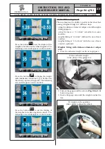
After making the wheel spin in ALU-S mode, the moni-
tor shows the total of 2 adhesive weights to precisely 
correct STATIC and DYNAMIC unbalance.

It is possible to fit a single weight at a predetermined 
distance from the machine, so as to optimize the weight 
consumption and reduce both the DYNAMIC and any 
remaining STATIC unbalance as much as possible.
Unlike  the  standard  STATIC  procedure,  the  ECO-
WEIGHT  procedure,  though  only  using  one  weight, 
also  considerably  reduces  the  DYNAMIC  unbalance, 
because the fitting distance of the weight on the rim 
is also calculated.
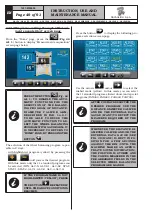
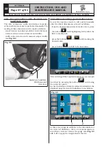
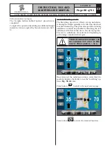
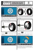
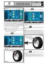
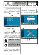
From ALU-S unbalance results page, if there is con-

siderable static unbalance, press the button 

 to 

display on the following monitor screen:

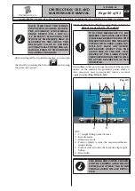
Press button 

 to select such procedure and bring 

automatically the wheel into weight fitting position.

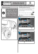
Fig. 61

1

2

3 4 5

6

KEY
1 – Only weight to be fitted
2 – Last program and last values used for the spin
3 – Residual dynamic unbalance value (if the value 

is yellow, it is not recommended to carry out 
ECO-WEIGHT procedure)

4 – Static unbalance value (if the value is yellow, it 

is not recommended to carry out ECO-WEIGHT 
procedure)

5 – Residual dynamic unbalance value (if the value 

is yellow, it is not recommended to carry out 
ECO-WEIGHT procedure)

6 – Arrows indicating the weight fitting point with 

distance-diameter caliper arm

1297-M058-00

G3.150 - GP3.150 - G3.150S - GP3.150S - G3.150WS - GP3.150WS - G3.150WSPLUS - GP3.150WSPLUS - G3.150SA - G3.150WSA

RAVAGLIOLI S.p.A.

Summary of Contents for G3.150

Page 1: ...ATION FROM THE ORIGINAL INSTRUCTIONS G3 150 GP3 150 G3 150S GP3 150S G3 150WS GP3 150WS G3 150WSPLUS GP3 150WSPLUS G3 150SA G3 150WSA 1297 M058 00 1297 M058 00 Technical services RAVAGLIOLI S p A Via...

Page 2: ...1 0 AIR CONNECTION __________________ 39 12 0 FITTING THE WHEEL ON THE CHUCK______________________________ 39 12 1 Wheel assembly________________________39 12 2 Wheel assembly________________________4...

Page 3: ..._76 15 3 1 Chuck 0 zero calibration________76 15 3 2 Weight measurement sensors calibration__________________________77 15 3 3 Gauges calibration__________________78 16 0 ERROR SIGNALS________________...

Page 4: ...LED light External data gauge Automatic width measuring device unit Car ring nut Tyre locking sleeve Off road vehicle cone D 88 132 Wheel protection disc Flange with gauge 12 o clock laser device OPT...

Page 5: ...RUCTION USE AND MAINTENANCE MANUAL EN Page 5 of 91 GENERAL DESCRIPTION Fig 1 1297 M058 00 G3 150 GP3 150 G3 150S GP3 150S G3 150WS GP3 150WS G3 150WSPLUS GP3 150WSPLUS G3 150SA G3 150WSA RAVAGLIOLI S...

Page 6: ...cking sleeve on models with pneumatic chuck 16 Cones protection cup 17 Manual caliper 18 Grippers for weights 19 Carriages counterweight 20 Fixed laser unit LED light standard on some models 21 Automa...

Page 7: ...ompulsorily Warning Be particularly careful possible material damages Symbols Description Danger Be particularly careful Note Indication and or useful information Move with fork lift truck or pal let...

Page 8: ...8 of 91 INSTRUCTION USE AND MAINTENANCE MANUAL INFORMATION PLATE LOCATION DRAWING G3 150 GP3 150 G3 150S GP3 150S G3 150WS GP3 150WS G3 150WSPLUS GP3 150WSPLUS G3 150SA G3 150WSA RAVAGLIOLI S p A 1297...

Page 9: ...onal on some models 999922780 Laser opening plate standard on some models 999922900 Manufacturer plate 999923160 Prop 65 warning plate standard on some models 999923190 Laser classification class 1 pl...

Page 10: ...e and care this wheel balancer will give you many years of trouble free service and lots of satisfaction 2 0 INTENDED USE The machines described in this manual and their different versions are wheels...

Page 11: ...on provided by the product may be impaired USE OF CONTROLS OR ADJUST MENTS OR PERFORMANCE OF PROCEDURES OTHER THAN THOSE SPECIFIED HEREIN MAY RESULT IN HAZARDOUS RADIA TION EXPOSURE APERTURE Side of p...

Page 12: ...e of potentially dangerous objects and that there is no oil since this could damage the tyre Oil on the floor is also a potential danger for the operator UNDER NO CIRCUMSTANCES must the machine be use...

Page 13: ...o cut along the lateral axis of the box and open it like a fan It is also possible to unnail the cardboard box from the pallet it is fixed to After removing the packing and in the case of the machine...

Page 14: ...se of the machine in ambient conditions other than those specified above is only allowed after prior agreement with and approval of the manufacturer 8 1 Working area Fig 3 USE THE MACHINE IN A DRY AND...

Page 15: ...ply with the following in structions for the assembly of the components making use of the attached series of illustrations 9 1 Anchoring system The packed machine is fixed to the support pallet throug...

Page 16: ...h an Allen wrench Fig 5 ref 1 on the flange Fig 5 ref 2 Fig 5 9 2 2 Fitting and removal of the pneumatic chuck on the flange On models with pneumatic chuck FITTING 1 After making power and air connect...

Page 17: ...e and turn the pneumatic shaft screw Fig _8 ref 1 onto the flange Fig _8 ref 2 until it stops Fig 8 5 Tighten with the wrench provided Fig _8 ref 3 REMOVAL 1 Open the pneumatic chuck by means of the p...

Page 18: ...n Support the casing Fig 12 ref 3 as shown in the figure and insert the monitor and keyboard cables Fig 12 ref 4 through the support pipe Fig 12 ref 5 2 Fit the support Fig 12 ref 5 complete with cas...

Page 19: ...uge arm are levelled out see Fig 16 Fig 15 3 Also make sure the gauge tip Fig 16 ref 1 is positioned at the centre of the chuck Fig 16 3 Fix the monitor Fig 13 ref 1 to the support Fig 13 ref 2 with t...

Page 20: ...nt the protection guard Fig 18 ref 1 to the support Fig 18 ref 2 using the screws Fig 18 ref 3 interposing the Belleville washers Fig 18 ref 4 and the tab washers Fig 18 ref 5 6 2 Tighten the screws F...

Page 21: ...ted in Fig 19 Eventually fasten connector s cable Fig 19 ref 3 with a clamp Fig 19 ref 5 Fig 19 9 2 7 Protection guard assembly with laser device 12 o clock optional 1 Fit the protective casing comple...

Page 22: ...2 o clock laser device proceed as follows 1 Mount a wheel to be balanced on the chuck 2 Take the wheel measurements in DYN mode and make the spin AT THE END OF THE SPIN THE LASER PLACED ON THE WHEEL C...

Page 23: ...onnection as shown in Fig 23 Fig 23 5 Fix the cables with clamps not to let them hinder the ordinary operation of the machine 6 Mount wheel balancer protection guard again FOR THE CONNECTIONS REFER TO...

Page 24: ...EFER TO WIRING DIAGRAMS 9 2 11Fitting of ultrasound Run out with sup port optional 1 Unscrew the fastening screws of the equalizer support Fig 24 ref 1 being very careful about holding the same suppor...

Page 25: ...E DOWN LOAD THE PROGRAM FROM THE AFTER SALES WEBSITE However a simple check can be made to make sure that everything is as it is expected to be 1 Before the Bluetooth device installation on the per so...

Page 26: ...e following screen appears where you can enter the password and the user number After entering the user number and password the following page will be displayed Press the Files Management highlighted...

Page 27: ...nter WARNING THE FOLLOWING WARNING SCREEN PAGE COULD BE DISPLAYED DURING THE IN STALLATION IN CASE IT APPEARS CLICK ON FURTHER INFORMATION AND IN THE FOLLOWING SCREEN PAGE ON PROCESS ANYWAY Proceed wi...

Page 28: ...t has been run the BTRemotePrinter icon is visible on the toolbar Printer Panel 4 3 2 1 5 6 7 8 KEY 1 Printer Panel is used when you need to carry out system configuration operations or to consult the...

Page 29: ...Report Config button to enter print layout personalization screen page Header text Line 1 Header text Lines 2 3 4 Fonts and header colours configuration Setting of User Logo 1297 M058 00 G3 150 GP3 1...

Page 30: ...e the configuration page and save it From now on all the following prints will appear with saved header If necessary before sav ing it is possible to run one or more test prints through the Print butt...

Page 31: ...ng for connection with PC mode see the following screen page Now work from the PC and run the research of the connectible machines Press Connections button to open the screen page of the available dev...

Page 32: ...f successful connection Finally save the configuration pressing the Save button Wait also for the machine to end the configuration Finally exit from the Printer Configuration menu On the display the n...

Page 33: ...appears completed in all its parts Date Time Vehicle Number plate could be incomplete or missing Balancing data Balancing graphs Progressive number Wheel balancer name User number 1297 M058 00 G3 150...

Page 34: ...s Client name Vehicle number plate Km Miles run Vehicle model At the end print report The data saving is performed anyway when the window is closed Particular remarks G3 150 GP3 150 G3 150S GP3 150S G...

Page 35: ...e of the list is named AA0000AA_2010_03_12_14_27_26 gz Therefore Number plate AA0000AA Report date 14 03 2010 at 14 27 26 In case there is no number plate the system names the files by linking togethe...

Page 36: ...PC Press Load Report You will see the following screen Store by number plate Number plates subgroups Data selection for number plate date from PC Press Load Report G3 150 GP3 150 G3 150S GP3 150S G3...

Page 37: ...ing screen Store by number plate Store by date Limited periods Anyway once the selection has been performed the data file is displayed in the usual way 1297 M058 00 G3 150 GP3 150 G3 150S GP3 150S G3...

Page 38: ...be performed by expert and professional personnel FIT A TYPE APPROVED AS RE PORTED BEFORE PLUG TO THE MACHINE CABLE THE GROUND WIRE IS YELLOW GREEN AND MUST NEVER BE CONNECTED TO ONE OF THE TWO PHASE...

Page 39: ...ORIES SPECIALLY DE SIGNED TO BE EMPLOYED WITH THE WHEEL BALANCERS ARE USED Wheel fitting using the cones provided is illustrated be low For alternative fittings using optional accessories refer to the...

Page 40: ...h the inside of the rim towards the wheel balancer until the wheel is up against the support flange Fig 31 ref 2 Fig 31 7 Fit the cone Fig 32 ref 3 with the narrowest part turned towards the wheel 8 F...

Page 41: ...g 34 ref 2 on the chuck Fig 34 ref 1 be careful otherwise this could seize until this rests against the support flange Fig 34 ref 4 3 Fit the wheel with the inner side of the rim towards the wheel bal...

Page 42: ...O KEEP YOUR HANDS AND OTH ER PARTS OF THE BODY AWAY FROM THE MOVING CHUCK 12 3 Adjustment of ultrasound sensor sup port standard on some models Ultrasound sensor support Fig 38 Fig 39 ref 1 must be us...

Page 43: ...move it to the position required as indicated in Fig 41 ref 1 At the end tighten the handwheel Fig 41 ref 2 1 Fig 40 4 3 2 5 Fig 41 1 2 IF ACTIVATED EACH TIME THAT THE WHEEL PROTECTION GUARD IS LOWER...

Page 44: ...ch Fig 27 ref 1 located in the rear part of the equipment IN THE CASE OF PNEUMATIC MODELS ON STARTING UP THE PNEUMATIC CHUCK IS ALWAYS OPENED ALWAYS KEEP YOUR HANDS AND OTHER PARTS OF THE BODY AWAY FR...

Page 45: ...see Chap 15 0 ounce weight displaying mode is set and push button will be displayed Press the button to set machine weight display in grams and on the screen will be displayed icon Press the button to...

Page 46: ...part of the rim 2 contact points see Fig Fig 46 to select ALU S program REPEATEDLY BRINGING THE CALIPER ARM FIG 47 REF 1 IN CONTACT WITH THE CHUCK FIG 47 REF 2 THE PROGRAM WILL CYCLE FROM ALU S TO AL...

Page 47: ...D FIELD OF THE CHOSEN BALANCING PROGRAM Fig 49 Measuring procedure of electronic RUN OUT with the distance diameter caliper arm The electronic RUN OUT measuring device is useful to check if the rim ha...

Page 48: ...on of the rim 12 o clock red 4 Value in mm of the highest peak of imperfection detected on the rim 5 Value in mm of imperfection of the rim at the current position 6 Value in mm of the lowest peak of...

Page 49: ...STAT 2 ALU 1 ALU 2 ALU 3 ALU 4 IF THE PROGRAM NAME IS NOT HIGHLIGHTED YELLOW PRESS THE BUTTON REPEATEDLY UNTIL THE ABOVE CONDITION IS REACHED Press the button to display the following pro grams select...

Page 50: ...TTING WITH FIXED LASER YOU WILL NOT HAVE ANY OTHER REFERENCE EXCEPT FOR THE CROSS LINE ON THE RIM GEN ERATED BY THE LASER ITSELF THE POSITIONING IN DEPTH WILL BE AT THE DISCRETION OF THE OPERATOR Depe...

Page 51: ...RAM HAVE NOT BEEN TAKEN INSERTED THE MACHINE DOES NOT ALLOW THE WHEEL SPIN TO DETECT THE UNBAL ANCE 14 4 Displaying the active modifiable field During the various phases of measures detection the acti...

Page 52: ...program to perform the spin and detect the values in P1 P2 P1 Weight to be fitted on rim outer side P2 Weight to be fitted on rim inner side 2 Wheel placed to fit the weight on wheel outer side arrow...

Page 53: ...page press the button to display the weight with maximum resolution 1g to be fitted on the wheel expressed in grams The following screen will appear on the moni tor Press again the button to display...

Page 54: ...ng weights fitting in 4 different ways using the distance diameter caliper arm with weights fitting grippers using the laser at 6 o clock standard on some models weights fitting at 6 o clock without t...

Page 55: ...IS MODE IT IS NECES SARY THAT THE RELEVANT FUNC TION IS ENABLED ON THE MENU OPTIONS DESCRIBED IN PAR 15 1 TO USE THIS WEIGHT APPLICA TION MODE THE OPERATOR MUST REMEMBER THE PRECISE POINT WHERE THE ME...

Page 56: ...tor depending on where remembers taking the measure BE SURE TO APPLY THE INTER NAL OR EXTERNAL WEIGHT AS INDICATED BY THE 2 GREEN ARROWS Fig 56 ref 2 or 3 ON THE CORRESPONDING MONITOR SCREEN Weights f...

Page 57: ...eed as follows from the desired measurement mode screen press the button until highlighting with yellow the field to modify edit press the buttons or until reaching the desired value press button to s...

Page 58: ...checked by performing a trial spin The procedure has now been completed 14 7 3Static 2 STATIC 2 function is a procedure that offsets wheel vibrations using a single adhesive weight on a single plane...

Page 59: ...orming a trial spin The procedure has now been completed 14 7 7ALU S2 ALU S2 function permits balancing wheels with light alloy rims by fitting two adhesive weights one on the outer and one on inner s...

Page 60: ...eel adhesive weight on outer side not visible because inside the rim Enter the measurements see Par 14 2 1 or 14 6 1 and proceed as for dynamic unbalance At the end of the procedure the wheel balancin...

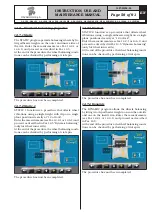
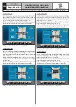
Page 61: ...uch as possible Unlike the standard STATIC procedure the ECO WEIGHT procedure though only using one weight also considerably reduces the DYNAMIC unbalance because the fitting distance of the weight on...

Page 62: ...WEIGHT procedure has now been completed IMMEDIATELY AFTER HAVING SELECTED THE ECO WEIGHT PROCEDURE YOU CAN KNOW IN ADVANCE THE TWO DYNAMIC UNBALANCES AND THE STATIC RESIDUE IN ORDER TO DECIDE WHETHER...

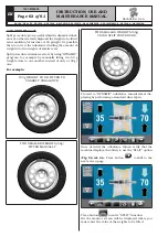
Page 63: ...nly a 100 gr one For example 100 g WEIGHT TO BE FITTED TO CORRECT UNBALANCE TWO SMALLER WEIGHTS 50g FITTED MANUALLY TWO SMALLER WEIGHTS 55g USING SPLIT PROCEDURE Proceed to DYNAMIC unbalance measureme...

Page 64: ...L IS PROP ERLY POSITIONED FOR THE AP PLICATION OF THE 1ST WEIGHT Fit the clip weight of the chosen value at 12 o clock on the outside of the wheel Press again button to position the wheel for the fitt...

Page 65: ...the total number of spokes If the value shown on the screen A is correct press the button The machine automatically calculates weight position in two positions hidden behind the spokes The moni tor sh...

Page 66: ...reducing unbalance as much as possible by offsetting the tyre unbalance with that of the rim in any used program Proceed to unbalance measurement displaying by performing a standard wheel spin THE MA...

Page 67: ...Remove the tyre and turn it on the rim through 180 Fit the wheel back on the wheel balancer positioning the reference mark on the rim in line with the arrow on the flange Position the reference mark o...

Page 68: ...erence mark on RIM Press the button to bring the wheel into posi tion Mark the reference mark on the TYRE at 12 o clock position Press button to confirm that step 3 has been completed STEP 4 Remove th...

Page 69: ...7 5 14 10 Recalculation function After making a spin the wheel automatically stops indicating the weight s to be fitted and its their position In case the operator does not want the type of wheel bala...

Page 70: ...he extension supplied with distance caliper extension kit kit available on demand THE EXTENSION MUST BE FIT TED ONLY WHEN BALANCING IS PERFORMED IN MOTORCYCLE MODE TO MOUNT THE EXTENSION AND THE COMPO...

Page 71: ...ONS WILL TURN BLUE WHEN THEY ARE SELECTED OPTIONS THAT ARE NOT AVAIL ABLE ARE MARKED WITH A RED X Enables disables the spin protection carter Enables disables the distance diameter detection caliper E...

Page 72: ...he functions of ma chine printing It allows you to change the unit of meas urement of the rim diameter from mm to inches and vice versa Enable disable the weights positioning laser function Enable dis...

Page 73: ...ult value 5 g 0 25 oz 2 Lower weight limit in the ALU STATIC program to display OK default value 7 g 0 35 oz 2 Weights display resolution default value 5 g 0 25 oz 4 Weight reduction in ECO WEIGHT fun...

Page 74: ...e last carried out spin B Acquired measurements for the last carried out spin Press any of the available numbers on the buttons at the bottom of the page to select the corresponding user The system st...

Page 75: ...llowing screen 1 KEY 1 Options menu push button Press button to display the monitor screen to enable disable the options as shown below Press button several times to display the second option screen p...

Page 76: ...2 ref 1 to display the following screen page on the monitor After making sure that the chuck is unloaded no wheel or mounted accessories and in the case of closed pneumatic chuck press the button and...

Page 77: ...CALLY AND THE SIZING SPIN IS CARRIED OUT At the end on the monitor will appear the following screen saying that you should apply a weight of 100 g to the 12 o clock outer rim APPLY THE WEIGHT AT A POI...

Page 78: ...apply it on the inner side at 12 o clock AT THIS POINT TAKE THE WEIGHT POSITIONED ON THE EXTERNAL SIDE AND PLACE IT EXACTLY IN THE SAME POSITION BUT ON THE INTERNAL SIDE HELPING BY DRAWING A LINE ON T...

Page 79: ...74 ref 2 must be equal to the value shown next to the scale symbol Fig _74 ref 1 1 mm Press push button The following screen will appear on the monitor Place the gauge as shown in the following figure...

Page 80: ...Fig 75 Fit the measured wheel on the balancer and lock it on the chuck Turn the gauge ferrule Fig 76 ref 1 on the inner edge of the wheel upwards see Fig _76 Fig 76 1 Press button to end the operatio...

Page 81: ...gauge standard on some models THE NUMERICAL VALUES SHOWN IN THE FIGURES BELOW ARE PURELY ILLUSTRATIVE Press the button to display the following screen page on the monitor TO PERFORM THIS CALIBRATION T...

Page 82: ...ING NUT DOES NOT OBSTRUCT THE READING OF THE SEN SOR DURING THE CALIBRATION PHASE SEE FIGURE BELOW Press the button to display the following screen page on the monitor Close the wheel cover until brin...

Page 83: ...el rotations not completed 10 Pneumatic chuck open 11 Incorrect gain calibration 12 Distance diameter caliper value not released 13 Distance diameter caliper value not released 14 Firmware error 15 Ru...

Page 84: ...r ANY DAMAGE TO THE MACHINE DEVICES RESULTING FROM THE USE OF LUBRICANTS OTHER THAN THOSE RECOMMENDED IN THIS MANUAL WILL RELEASE THE MANUFACTURER FROM ANY LIABILITY 17 0 ROUTINE MAINTENANCE BEFORE CA...

Page 85: ...echanical data Balancing precision g 1 Rim width inches 1 5 22 Rim diameter inches 10 26 manually up to 30 Max wheel diameter inches 43 Cycle time sec 6 Sound emission level dBA 70 Max wheel weight kg...

Page 86: ...SE AND MAINTENANCE MANUAL 18 3 Dimensions Fig 79 threaded chuck pneumatic chuck Standard on some models G3 150 GP3 150 G3 150S GP3 150S G3 150WS GP3 150WS G3 150WSPLUS GP3 150WSPLUS G3 150SA G3 150WSA...

Page 87: ...ken not to make further use of the machine it is advisable to make it inoperative by removing the connection pressure pipes The machine is to be considered as special waste and should be dismantled in...

Page 88: ...NTER KIT series SELF CENTRING CHUCK PNEUMATIC LED LIGHT CALIPER DIAMETER POTENTIOMETER RUN OUT POTENTIOMETER WIDTH WHITE AUTOMATIC WIDTH Connection mode without LASER AT 12 O CLOCK see NOTE A otherwis...

Page 89: ...on GAR308 29 Width potentiometer extension cable on GAR303 GAR305 GAR307 30 Width cables on GAR303 GAR305 31 Potentiometer with shielded cable on GAR307 32 Run out push button cables on GAR303 33 Run...

Page 90: ...TION DIAGRAM Drawing N B Rev 0 129600170 EVO EVC 1 2 3 4 KEY 1 Pneumatic self centring chuck 2 Pneumatic tightening system 3 Solenoid valve unit 4 Filter mounting RAVAGLIOLI S p A 1297 M058 00 GP3 150...

Page 91: ...DISPOSITION Drawing N C Rev 0 Wi Fi kit Printer kit 12 o clock laser Read out card kit Run out CPU card kit RAVAGLIOLI S p A 1297 M058 00 G3 150 GP3 150 G3 150S GP3 150S G3 150WS GP3 150WS G3 150WSPLU...

Page 92: ...n Normen entspricht objet de cette d claration est conforme aux Directives applicables suivantes al que se refiere esta declaraci n cumple con las siguientes Normas aplicables 2006 42 CE Direttiva Mac...

Reviews: