EN
Page 18 of 91
INSTRUCTION, USE AND
MAINTENANCE MANUAL
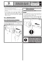
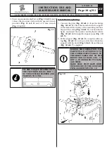
3. Unscrew pneumatic shaft screw (
Fig.
_
11 ref. 1
) and
release the two inner rods with the special wrench
provided (
Fig.
_
11 ref. 2
) and a 12 mm wrench
(
Fig.
_
11 ref. 3
).
Fig. 11
FIT THE TORQUE SPANNER INTO
THE PROVIDED HOLES (REF. 1)
OF THE SUPPLIED SPANNER AND
TIGHTEN TO 30 NM.
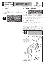
9.2.3 Monitor fitting
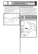
1. Unscrew the plate (
Fig. 12 ref. 1
) from the bridge
(
Fig. 12 ref. 2
). Place the monitor with its support
in the immediate vicinity of the mounting location.
Support the casing (
Fig. 12 ref. 3
), as shown in the
figure, and insert the monitor and keyboard cables
(
Fig. 12 ref. 4
) through the support pipe (
Fig. 12
ref. 5
).
2. Fit the support (
Fig. 12 ref. 5
), complete with cas-
ing (
Fig. 12 ref. 3
), in the provided seat. Block the
support with the dowel (
Fig. 12 ref. 6
) and the nut
(
Fig. 12 ref. 7
), supplied.
DURING THIS OPERATION, PAY
PARTICULAR ATTENTION TO
THE POWER SUPPLY CABLE, TO
THE HDMI CABLE AND TO THE
KEYBOARD CABLES
(
FIG. 12
REF. 4
)
IN ORDER NOT TO DAM-
AGE THEM.
MAKE SURE THEY HAVE BEEN
INTRODUCED IN THE SUPPORT
PIPE, AS SHOWN IN FIG. 12.
Fig. 12
G3.150 - GP3.150 - G3.150S - GP3.150S - G3.150WS - GP3.150WS - G3.150WSPLUS - GP3.150WSPLUS - G3.150SA - G3.150WSA
RAVAGLIOLI S.p.A.
1297-M058-00

