EN
Page 50 of 91
INSTRUCTION, USE AND
MAINTENANCE MANUAL
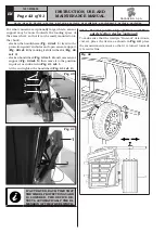
EACH TIME THAT THE WHEEL
PROTECTION GUARD IS CLOSED;
THE AUTOMATIC WIDTH MEAS-
URING DEVICE (FIG. 1 REF. 21)
(IF PRESENT) MEASURES THE
WIDTH OF THE WHEEL THAT IS
MOUNTED ON THE CHUCK. THE
RELEVANT VALUE IS STORED
AUTOMATICALLY IN THE PRE-AR-
RANGED FIELD OF THE CHOSEN
BALANCING PROGRAM.
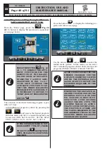
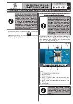
- After entering all the required measures, you can spin
the wheel by pressing the button
and closing
the protective guard.
14.3 Indicative display of points where to
detect measures/to fit weight
IT IS VERY IMPORTANT TO RE-
MEMBER THE POINTS SELECTED
FOR MEASUREMENT INSIDE THE
RIM SINCE DURING THE WEIGHTS
FITTING WITH FIXED LASER YOU
WILL NOT HAVE ANY OTHER
REFERENCE EXCEPT FOR THE
CROSS LINE ON THE RIM, GEN-
ERATED BY THE LASER ITSELF.
THE POSITIONING IN DEPTH WILL
BE AT THE DISCRETION OF THE
OPERATOR.
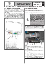
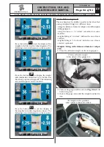
Depending on the type of program selected,the machine
shows on the monitor the guideline points where to
take measures and, consequently, where you must
apply weights (
Fig. 55 ref. 4-5
).
Fig. 55
2
5
1
5
3
4
6
KEY
1 – 1
st
weight fitting point distance
2 – Rim diameter
3 – Balancing mode
4 – Point at which to take the measure/adhesive
weight fitting
5 – Point at which to take the measure/clip weight
fitting
6 – Rim width
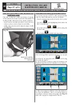
THE MORE THE POINTS CHOSEN
FOR THE PROBING ARE DISTANT
FROM EACH OTHER THE MORE
THE BALANCING WILL BE EFFEC-
TIVE.
G3.150 - GP3.150 - G3.150S - GP3.150S - G3.150WS - GP3.150WS - G3.150WSPLUS - GP3.150WSPLUS - G3.150SA - G3.150WSA
RAVAGLIOLI S.p.A.
1297-M058-00

