INSTRUCTION, USE AND
MAINTENANCE MANUAL
EN
Page 77 of 91
15.3.2 Weight measurement sensors calibra-
tion
THE NUMERICAL VALUES SHOWN
IN THE FIGURES BELOW ARE
PURELY ILLUSTRATIVE.
ASSEMBLE A BALANCED WHEEL
ON THE SPINDLE AND PER-
FORM THE SPINDLE “0” (ZERO)
CALIBRATION PROCEDURE DE-
SCRIBED IN PAR. 15.3.1 (WITH
WHEEL MOUNTED).
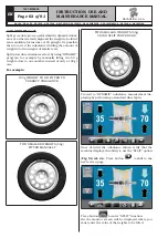
- Press the button
(
Fig. 72 ref. 2
) to display
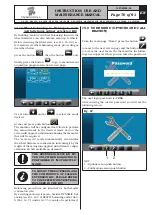
the following screen page on the monitor:
- Set the size of the rim on the chuck using the dis-
tance-diameter caliper arm.
- Set the rim width using one of the following calipers:
• Manual caliper
• External data gauge (standard on some models)
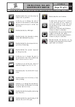
- Press button
and close the guard to the per-
form the 1st spin of the wheel without weights.
IN THE VERSIONS WITH AUTO-
MATIC WIDTH MEASURING DE-
VICE, WHEN THE GUARD IS LOW-
ERED, THE RIM WIDTH IS MEAS-
URED AUTOMATICALLY AND THE
SIZING SPIN IS CARRIED OUT.
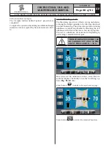
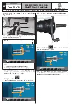
- At the end, on the monitor will appear the following
screen, saying that you should apply a weight of 100
g to the "12 o'clock" outer rim.
APPLY THE WEIGHT AT A POINT
IN WHICH BOTH SIDES OF THE
RIM THERE IS THE POSSIBILITY
OF APPLYING A CLIP WEIGHT OF
100 g.
- Apply the weight and position it perfectly to the "12
o'clock".
- Press the button
and close the guard to per-
form the 2nd spin of the wheel (100 g weight placed
on the outside of the wheel).
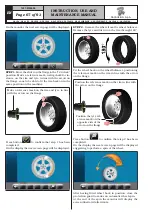
- At the end the following screen will appear on the
monitor, suggesting to remove the weight of 100 g
previously applied on the outer side and apply it on
the inside of the rim.
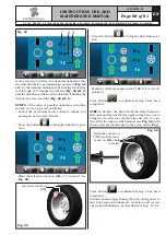
- Turn manually the wheel until You have the weight
of 100 g on the outer side at "12 o'clock".
- Press the brake pedal and hold it down during the
whole the following operation to avoid unexpected
rotation of the spindle.
1297-M058-00
G3.150 - GP3.150 - G3.150S - GP3.150S - G3.150WS - GP3.150WS - G3.150WSPLUS - GP3.150WSPLUS - G3.150SA - G3.150WSA
RAVAGLIOLI S.p.A.

