background image

 
Introduction 

User Manual 

ApplianceStor 50   

Rev. 1, November 2011


9

Internal 

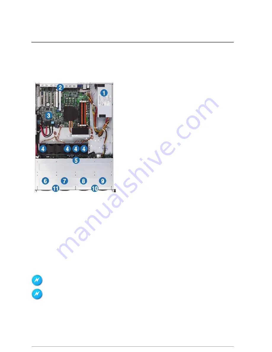
The AS50 server includes the basic components as shown. 

Figure 3- Internal view 


1.


   Power supply and power fan 

2.


   PCI Express slot Riser Card 

3.


   RASILIENT SYSTEMS P8B-E/4L server boards 

4.


   System fans 

5.


   SAS / SATA backplane (hidden) 

6.


   HDD tray 1—Connect to SATA1 port (SATA 6Gb/s) 

7.


   HDD tray 2—Connect to SATA2 port (SATA 6Gb/s) 

8.


   HDD tray 3—Connect to SATA3 port 

9.


   HDD tray 4—Connect to SATA4 port 

10.


Front I/O boards (hidden)   

11.


Slim-type optical drive 

Turn off the system power and detach the power supply before removing replacing any system component. 

WARNING HAZARDOUS MOVING PARTS KEEP FINGERS AND OTHER BODY PARTS AWAY


Summary of Contents for ApplianceStor 50

Page 1: ...Manual contents ApplianceStor50 Performance Storage Server User Manual 1th Edition November 2010 ...

Page 2: ... product herein Nothing herein may be construed as granting any right or license relating to any intellectual property rights of this manual or product Unless otherwise provided in the Purchase and Sale Agreement for this product manufacturer and distributor of this product will not be liable whatsoever relating to the distribution and or use of this product In addition manufacturer and distributo...

Page 3: ...mbers vi Product Regulatory Compliance vi Power Cords viii Introduction 2 Audience Assumptions 2 About This Guide 2 Product introduction 3 System Description 3 Simple 3 Powerful 3 Reliable 3 Right Size 4 Performance 4 Open 4 Green 4 Optimized 4 Easy 4 Expandable 5 System Specification 5 System Layout 7 LED 10 Before You Begin 13 Gather information 13 Packing Checklist 13 Hardware Preparation and I...

Page 4: ...RAID controller driver 38 Intel chipset device software installation 40 LAN driver installation 44 VGA driver installation 48 Management applications and utilities installation 51 Configurations 54 Jumpers 54 Connectors 59 Internal connectors 60 Internal LEDs 69 Appendix B BIOS Configurations 70 Managing and updating your BIOS 70 CrashFree BIOS 3 utility 70 RASILIENT SYSTEMS EZ Flash Utility 70 BU...

Page 5: ... 15 Figure 9 Rail assembly 15 Figure 10 Rails and rack installation 16 Figure 11 install server in rack 16 Figure 12 secure server to rack 17 Figure 13 Remove server from rack 17 Figure 14 remove chassis cover 18 Figure 15 rear thumb screws 18 Figure 16 Remove protective tape 18 Figure 17 RAM sockets 19 Figure 18 DIMM insertion 20 Figure 19 DIMM lock 20 Figure 20 DIMM removal 20 Figure 21 HD carri...

Page 6: ...ry disk 34 Figure 45 Install RAID driver 36 Figure 46 Install RAID driver 36 Figure 47 Select OS for RAID driver 37 Figure 48 Install windows controller driver 38 Figure 49 Windows setup 38 Figure 50 Insert disk 39 Figure 51 Verify driver installation 40 Figure 52 Intel Chipset install 41 Figure 53 Intel Chipset Device 41 Figure 54 Installer License Agreement 42 Figure 55 Installer readme file 42 ...

Page 7: ... Figure 85 Hard disk activity LED 61 Figure 86 USB connector 61 Figure 87 CPU front and rear fan connectors 63 Figure 88 Serial General Purpose Input Output 63 Figure 89 Serial General Purpose Input Output connectors 64 Figure 90 Serial port connectors 64 Figure 91 BMC header 64 Figure 92 Power Supply SMBus 65 Figure 93 TPM connector 65 Figure 94 ATX power 66 Figure 95 Parallel port 66 Figure 96 S...

Page 8: ...TXT 87 Figure 119 USB configuration 88 Figure 120 Onboard devices 89 Figure 121 APM 90 Figure 122 Serial Port Console redirect 91 Figure 123 Notwork Stack 93 Figure 124 System Monitor 94 Figure 125 Boot Menu 95 Figure 126 EZ Flash 97 Figure 127 EZ flash exit 97 List of Tables Table 1 Product Safety Requirements vi Table 2 European Union Safety Requirements vii Table 3 Manual Organization 2 Table 4...

Page 9: ...About This Manual Conventions Safety Symbols Safety Precautions Regulatory and Integration Information ...

Page 10: ...行特定工作 請注意本手冊中所使用的下列符號 Warning 警告 警告 警告 警告 Provides Information to prevent injury in the process of completing a task 在完成工作過程中所提供的傷害預防資訊 Caution 注意 注意 注意 注意 Provides Information to prevent damage to the components in the process of completing a task 在完成工作過程中所提供的元件損壞預防資訊 Important 重要 重要 重要 重要事項 事項 事項 事項 Provides Information required for completing a task 提供完成工作的必要資訊 Note 附註 附註 附註 附註 Provides Tips to...

Page 11: ...le e g RJ45 marked with this symbol indicates a network interface connection To reduce the risk of electric shock fire or damage to equipment do not plug telephone or telecommunications connectors into this receptacle 警告 警告 警告 警告 僅能插入網路介面 任何標示本符號的插座 例如 RJ45 皆代表為網路 介面連線 為降低觸電 火災或設備損壞的風險 請勿將電話或電信接頭插入 本插座 WARNING This symbol on power supplies or systems indicates that the equipment is supplied by mul...

Page 12: ...printed wiring board Improper repairs can create a safety hazard 所有修理程序皆僅能進行模組更換 由於個別電路板及子組件極為複雜 任何人皆不 應執行元件層級的修理 或對任何印刷電路板進行修改 不當的修理可能會造成安全 性危險 To reduce the risk of personal injury from electric shock and hazardous energy levels do not exceed the level of repairs specified in these procedures 為降低因觸電及危險能量等級所導致人身傷害或設備損壞的風險 請勿超出維修程序 所規定的維修等級 The system is designed to be electrically grounded To ens...

Page 13: ...區域中的所有非傳導性材質 例如一般的塑膠工具及泡棉包裝材料 Avoid touching pins leads or circuitry 請避免碰觸任何接腳 導線或電路 Always place drives with printed circuit board PCB assembly side down 請以印刷電路板 PCB 組件側朝下放置磁碟機 Grasp cards and boards by the edges Hold drives by the frame Avoid touching the solder joints or pins 請由邊緣握住卡片及電路板 手持磁碟機的邊架 並避免碰觸焊接點或接腳 If you need to lay the device down while it is out of the antistatic bag lay it on the...

Page 14: ...ent plugged into the extension cable or power strip does not exceed 80 percent of the ampere ratings limit for the extension cable or power strip System Warnings Avoid dust humidity and extreme temperatures place the system on a stable surface To reduce the risk of personal injury from hot surfaces allow the hot plug disk modules and other system modules to cool before touching them To reduce the ...

Page 15: ...Including Electrical Business Equipment European Committee for Electro technical Standardization CENELEC UL 60950 1 Safety of Information Technology Equipment UL 94 Tests for Flammability of Plastic Materials for Parts in Devices Appliances GB4943 Safety of Information Technology Equipment Worldwide Safety approvals can be supplied upon request Please contact your sales representative for approval...

Page 16: ...and if not installed and used in accordance with the instructions may cause harmful interference to radio communications Operation of this equipment in a residential area is likely to cause harmful interference in which case the user will be required to correct the interference at personal expense Declaration of Conformity for Products Marked with the FCC Logo United States Only This device compli...

Page 17: ...untry contact your sales representative to purchase a power cord that is approved for use in that country The power cord must be rated for the product and for the voltage and current marked on the product s electrical ratings label The voltage and current rating of the cord should be greater than the voltage and current rating marked on the product In addition the cross sectional area of the wires...

Page 18: ...ber 2011 ix The following statement applies only to rack installed products that are GS Marked This equipment is not intended for use at workplaces with visual display units in accordance with 2 of the German ordinance for workplaces with visual display units ...

Page 19: ...Introduction User Manual ApplianceStor 50 Rev 1 November 2011 1 Audience Assumptions About This Guide Description Features Specifications Chapter 1 Introduction ...

Page 20: ... the ApplianceStor 50 SAN Storage Server This manual is generally organized as follows Table 3 Manual Organization Introduction General introduction to the AS50and its components Preparation What you need to do before you start Installation Detailed description of each hardware module and instructions for installation and removal Configuration Initializing your system setting up your system on a n...

Page 21: ...ration Intel Sandy Bridge Xeon quad core processors and fast DDR3 memory The AS50 offers high performance and bandwidth connectivity to meet the most demanding megapixel camera applications The base AS50 model unmatched LAN connectivity with 4 GbE ports and an addition port that can be dedicated to management for a total of 5GbE LAN ports With the AS50 Video Surveillance Appliance un matched LAN c...

Page 22: ...e a huge increase in video surveillance performance over previous generation processors Open The AS50 is a designed and optimized to integrate Video Management Software We have prequalified all major OS and VMS providers We continually add more to ensure the widest possible product certification coverage Green Green drive technology provides a 32 drive power reduction AS50 power consumption is fur...

Page 23: ...nology CPU Type Intel Sandy Bridge Xeon E3 1200 Socket LGA1155 Core Logic Intel C204 Chipset Memory size 8GB 2x4GB Memory type DDR3 1333 ECC UDIMM Expansion xpansion xpansion xpansion Expansion Slot 2 Slot Type 1xPCI Ex16 Gen2 X16 Link Full Height Half Length 1 xPCI Ex8 Gen1 X4 Link Full Height Half Length Internal slot Storage Enhancement Storage Storage Storage Storage HDD Bays 4 x Hot swap 3 5 ...

Page 24: ...366 EEC EMI US FCC CFR47 Part 15 Class A Europe CE EN55022 EN55024 Australia C TICK Taiwan BSMI China CCC Physical Characteristics Physical Characteristics Physical Characteristics Physical Characteristics Dimensions in mm 24 2 x 17 5 x 1 7 380 x 430 x 43 4 Weight 33lbs 6 5Kg Power Power Power Power Voltage 110 220V AC Watts 350 Operating Environment Operating Environment Operating Environment Ope...

Page 25: ...reachNodearelocatedonthefrontpanel Figure 1 Front panel Turnoffthesystempoweranddetachthepowersupplybeforeremovingor Turnoffthesystempoweranddetachthepowersupplybeforeremovingor Turnoffthesystempoweranddetachthepowersupplybeforeremovingor Turnoffthesystempoweranddetachthepowersupplybeforeremovingorreplacinganysystem replacinganysystem replacinganysystem replacinganysystem component component compo...

Page 26: ...stheexpansionslots systempowersockets andrearfans TheI Oshieldswithopeningsforthe rearpanelconnectorsonthemotherboardarealsoplacedintherealpanel Figure 2 Rear panel layout Thep Thep Thep Theports orts orts ortsfortheUSB VGA and GigabitLANsdo notappearontherearpanelifthemotherboardsarenotpresent ...

Page 27: ...TEMSP8B E 4Lserverboards 4 Systemfans 5 SAS SATAbackplane hidden 6 HDDtray1 ConnecttoSATA1port SATA6Gb s 7 HDDtray2 ConnecttoSATA2port SATA6Gb s 8 HDDtray3 ConnecttoSATA3port 9 HDDtray4 ConnecttoSATA4port 10 FrontI Oboards hidden 11 Slim typeopticaldrive Turnoffthesystempoweranddetachthepowersupplybeforeremovingreplacingany systemcomponent WARNING HAZARDOUS MOVING PARTS KEEP FINGERS AND OTHER BODY...

Page 28: ...Introduction User Manual ApplianceStor 50 Rev 1 November 2011 10 LED Front panel LEDs Figure 4 Front panel LEDs Table 4 LED description Hard Drive Status LED Figure 5 Hard drive LEDs ...

Page 29: ...Introduction User Manual ApplianceStor 50 Rev 1 November 2011 11 LAN RJ 45 LEDs Figure 6 NIC LEDs ...

Page 30: ...Packing Checklist Chapter 2 Before You Begin ...

Page 31: ...an properly configure your system on your network IP Address s Gateway address Net mask address DNS server information Packing Checklist Make sure you have all the components that shipped with your system If any item is damaged or missing please contact your sales representative for a replacement The AS50 is shipped with the following Table 5 Packing Checklist Check your system package for the fol...

Page 32: ...Hardware Installation Rev 1 November 2011 User Manual ApplianceStor 50 14 Installing Hardware Modules Installing in a Rack Installing RAM Drives and expansion boards Chapter 3 Hardware Installation ...

Page 33: ...er to the image belowfor the locationsto attach the two fixing latchesto the two sidesof the server with four screws Figure 8 Rail Latches Attaching the rack rails To attach the rack rails 1 Place the two front rail rack joints into the rear rail rack slots as shown in the following figure 2 Attach the front and rear rail racks with eight screws and nuts as shown in the following figure Do not sec...

Page 34: ...goes to the front of the rack space Figure 10 Rails and rack installation 7 Secure the front end of the rail with two rack screws as shown in the right figure 8 Secure the rear end of the rail with two rack screws as shown in the right figure 9 Fasten the eight screw you secure in step 2 as shown in the right figure 10 Repeat steps 6 to 9 to assemble and attach the rack rail on the other side Moun...

Page 35: ... Figure 12 secure server to rack 3 Tighten the two rack screwsto secure the server in place To uninstall the server from the rack 1 Loosen the rack screwsthatsecured the server to the rack 2 Pull the server from the rack Figure 13 Remove server from rack Remember to press the latches on both sides to release the server from the rack ...

Page 36: ...oward the rear panel for about half an inch until it is disengaged from the chassis 4 Lift the cover from the chassis 5 To recover the rear cover reverse step 1 to 4 Aprotectionfilmispre attachedto the system cover before shipping Please remove the protection film before turning on thesystem for properheatdissipation Figure 16 Remove protective tape System memory Overview The motherboardcomeswith ...

Page 37: ... configurationsin thissection Table 6 RAM installation Start installing the DIMMs from slot A2 and B2 orange Always install DIMMs with the same CAS latency For optimum compatibility it is recommended that you obtain memory modules from the same vendor Installing a DIMM Ensure to unplug the power supply before adding or removing DIMMsor other system components Failure to do so may cause severe dama...

Page 38: ...lock Always insert the DIMM into the socket VERTICALLY to prevent DIMM notch damage 3 Hold the DIMM by both of its ends then insert the DIMM vertically into the socket Apply force to both ends of the DIMM simultaneously until the retaining clips snap back into place and the DIMM cannot be pushed in any further to ensure proper sitting of the DIMM Removing a DIMM 1 Simultaneously press the retainin...

Page 39: ...ackplane To install ahot swapSATA SASHDD 1 Release a drive tray by pushing the spring lock to the right then pulling the tray lever outward The drive tray ejects slightly after you pull out the lever Figure 21 HD carrier unlatch 2 Firmly hold the tray lever and pull the drive tray out of the bay Figure 22 HD carrier open 3 Take note of the drive tray holes Each side has three holes to fit differen...

Page 40: ...tray and push it all the way to the depth of the bay until just a small fraction of the tray edge protrudes Figure 25 Install carrier and drive 6 Push the tray lever until it clicks and secures the drive tray in place The drive tray is correctly placed when its front edge aligns with the bay edge 7 Repeat steps 1 to 6 if you wish to install a second SATA SAS drive Expansion slot Installing an expa...

Page 41: ... 1 Firmly holdthe riser card bracket then pullit up to detach itfrom the PCI Expressx16 sloton the motherboard Figure 27 disassemble riser assembly 2 Place the riser cardbracket on aflatand stable surface then remove the screwfrom the slotbay Figure 28 install expasion card 3 Install a PCI Expressx8 or x16 cardto the bracketas shown then secure the cardwith a screw 4 Repeatthe previoussteps to Ins...

Page 42: ...tall riser and expansion card 1 Align the riser cardbracket with the cards to the PCI Expressx16 sloton the motherboard 2 Pressthe riser card bracketuntil the golden connectorscompletely fit the slot andthe bracket aligns with the rear panel 3 Connectthe cable s to the card if applicable ...

Page 43: ...Hardware Installation User Manual ApplianceStor 50 Rev 1 November 2011 25 4 RAID Setup Configure the System Additional Configuration Options Chapter 4 System Configuration ...

Page 44: ...The new drive must be of the same size or larger than the existing drive RAID 10 RAID 10 RAID 10 RAID 10 is data striping and data mirroring combined without parity redundancy data having to be calculated and written With the RAID 10 configuration you get all the benefits of both RAID 0 and RAID 1 configurations Use four new hard disk drives or use an existing drive and three new drives for this s...

Page 45: ... BIOS Setup during POST BIOS Setup during POST BIOS Setup during POST BIOS Setup during POST 2 Go to the Advanced Advanced Advanced Advanced Menu SATA Configuration SATA Configuration SATA Configuration SATA Configuration then press Enter 3 Set SATA Mode SATA Mode SATA Mode SATA Mode to RAID Mode 4 Press F10 to save your changes and exit the BIOS Setup RefertoChapter 5fordetailsonenteringandnaviga...

Page 46: ...nology option ROM utility 1 Install all the Serial ATA hard disk drives 2 Turn on the system 3 During POST press Ctrl l to display the utility main menu Figure 30 RAID GUI The navigation keys at the bottom of the screen allow you to move through the menus and select the menu options TheRAIDBIOSsetupscreensshowninthissectionareforreferenceonlyandmay notexactly match the items on yourscreen Creating...

Page 47: ...iangle marks the selected drive Press Enter after completing your selection 6 Use the up down arrow keys to select the stripe size for the RAID array for RAID 0 10 and 5only and then press Enter The available stripe size values range from 4 KB to 128 KB The following are typical values oRAID 0 128KB oRAID 10 64KB oRAID 5 64KB We recommend a lower stripe size for server systems and a higher stripe ...

Page 48: ... utility main menu select 1 Create RAID Volume and press Enter The following screenappears Figure 34 Create Recovery Set 2 Enter a name for the recovery set and press Enter 3 When the RAID Level item is selected press the up down arrow keys to select Recovery and then press Enter 4 When the Disks item is selected press Enter to select the hard disk drives you want to include in the recovery set Th...

Page 49: ...Set create volume 8 Press Y to create the recovery set and return to the main menu or N to go back to the CREATE VOLUME menu If a recovery set is created you cannot add more RAID sets even when you have more non RAID disks installed in your system Deleting a RAID set Take caution when deleting a RAID set You will lose all data on the hard disk drives whenyou delete a RAID set To delete a RAID set ...

Page 50: ...setDisks to Non 3 ResetDisks to Non RAID RAID RAID RAID and press 2 Enter The following screenappears Figure 39 Reset Disks 3 Usetheup downarrowkeystoselecttheRAIDsetdrive s youwanttoreset and then press Space toselect 4 Press Enter toresettheRAIDsetdrive s Aconfirmationmessageappears 5 Press Y toresetthedrive s orpress N toreturntotheutilitymainmenu Recovery Volume Options If you have created a r...

Page 51: ...electadrive andthenpress Space toselect Asmalltrianglemarks theselecteddrive Press Enter aftercompletingyourselectionandreturntotheutilitymainmenu Exiting the Intel Rapid Storage Technology utility To exit the utility 1 Fromtheutilitymainmenu select5 Exit andthenpress Enter Thefollowingwarningmessageappears Figure 42 Execute recovery volume 2 Press Y to exit or press N to return to the utility mai...

Page 52: ... If there is a non RAID SATA Hard Disk available the utility will prompt to rebuild the RAID Press Enter and then use up down arrow keys to select the destination disk or press ESC to exit Figure 43 Rebuild RAID Select a destination disk with the same size as the original hard disk 3 The utility immediately starts rebuilding after the disk is selected The status Figure 44 Select recovery disk 4 of...

Page 53: ...ame specification into the same SATA Port Select a destination disk with the same size as the original hard disk 2 Reboot the system and then follow the steps in section Rebuilding the RAID with other non RAID disk Setting the Boot array in the BIOS Setup Utility YoucansetthebootprioritysequenceintheBIOSforyourRAIDarrayswhencreating multi RAID using theIntel RapidStorageTechnology Tosetthe bootarr...

Page 54: ...sted Otherwise the system will not boot from the connected SATA ODD A floppy disk with the RAID driver is required when installing Windows or Red Hat Enterprise operating system on a hard disk drive that is included in aRAIDset YoucancreateaRAIDdriver disk inDOS using the Makediskapplication inthe supportDVD To create a RAID driver disk in DOS environment 1 Place the motherboard support DVD in the...

Page 55: ...the Make disk menu and then select the type of RAID driver disk you want to create 4 Insert a floppy disk into the USB floppy disk drive 5 Follow succeeding screen instructions to complete the process Write protect the floppy disk to avoid computer virus infection To create a RAID driver disk in Red Hat Enterprise Linux server environment 1 Insert a blank formatted high density floppy disk to the ...

Page 56: ...lingWindows ServerOS 1 Boot the computer using the Windows Server installation DVD The Windows Server OS Setup starts Figure 48 Install windows controller driver 2 Press F6 when the message Press F6 if you need to install a third party SCSI or RAID driver appears at the bottom of the screen 3 When prompted press S to specify an additional device Figure 49 Windows setup 4 Insert the RAID driver dis...

Page 57: ... Click the Hardware tab and then click the Device Manager Button to display the list of devices installed in the system 5 Right click the RAID controller item then select Properties 6 Click the Driver tab and then click the Update Driver button 7 The Upgrade Device Driver Wizard window appears Click Next 8 Insert the RAID driver disk you created earlier to the floppy disk drive 9 Selectthe optionI...

Page 58: ...oinstalltheIntele chipsetdevicesoftware on the system YouneedtomanuallyinstalltheIntel chipsetdevicesoftwareonaWindowsoperating system Toinstall the Intel chipsetdevice software 1 Restart the computer and then log on with Administrator privileges 2 Insert the motherboard system support DVD to the optical drive The support DVD automatically displays the Drivers menu if Autorun is enabled in your co...

Page 59: ...or 50 Rev 1 November 2011 41 Figure 52 Intel Chipset install 4 The Intel R Chipset Device Software window appears Click Next to start installation Figure 53 Intel Chipset Device 5 SelectYestoacceptthetermsoftheLicenseAgreementandcontinuetheprocess ...

Page 60: ...tor 50 Rev 1 November 2011 42 Figure 54 Installer License Agreement 6 ReadtheReadmeFileInformationandpressNexttocontinuetheinstallation Figure 55 Installer readme file 7 After completing the installation click Finish to complete the setup process ...

Page 61: ...Hardware Installation User Manual ApplianceStor 50 Rev 1 November 2011 43 Figure 56 Finish chipset install ...

Page 62: ...ministrator privileges 2 Insertthemotherboard systemsupportDVDtotheopticaldrive ThesupportDVDautomatically displaystheDriversmenuifAutorunisenabledinyourcomputer Windows automatically detects the LAN controllers and displays a New Hardware Found window Click Cancel to close this window If Autorun is NOT enabled in your computer browse the contents of the support DVD to locate the file ASSETUP EXE ...

Page 63: ...nceStor 50 Rev 1 November 2011 45 4 ClickNextwhentheIntelNetworkConnections InstallShieldWizardwindowappears Figure 58 Install Shield Wizard 5 ToggleIacceptthetermsinthelicencseagreementandclickNexttocontinue Figure 59 Install Wizard read me ...

Page 64: ...Rev 1 November 2011 46 6 ClicktheIntel R PROSetforWindowsDeviceManagerbox andthenclickNexttostartthe installation Figure 60 Select options 7 Followthescreeninstructionstocompleteinstallation Figure 61 Install driver 8 Whenfinished pressFinishtocontinue ...

Page 65: ...Hardware Installation User Manual ApplianceStor 50 Rev 1 November 2011 47 Figure 62 Install finish ...

Page 66: ...henlogonwithAdministratorprivileges 2 Insertthemotherboard systemsupportDVDtotheopticaldrive ThesupportDVDautomatically displaystheDriversmenuifAutorunisenabledinyourcomputer If Autorun is NOT enabled in your computer browse the contents of the support DVD to locate the file ASSETUP EXE from the BIN folder Double click the ASSETUP EXE to run the support DVD 3 ClicktheASPEEDAST2050DisplayDrivertobe...

Page 67: ...1 November 2011 49 5 ToggleIacceptthetermsinthelicenseagreementandclickNexttocontinue Figure 65 License Agreement 6 EntertheuserinformationandclickNexttocontinue Figure 66 Customer information 7 SelectasetuptypeandclickNexttocontinue Figure 67 Install type ...

Page 68: ...er Manual ApplianceStor 50 Rev 1 November 2011 50 8 ClickInstalltostartdriverinstallation Figure 68 Install driver 9 Whentheinstallationcompletes clickFinishtorestartyourcomputerbeforeusingtheprogram Figure 69 Complete install ...

Page 69: ...ww Rasilient Systems com for updates Running the support DVD PlacethesupportDVD tothe optical drive The DVDautomatically displays theDrivers menu if Autorun is enabled inyour computer If Autorun is NOT enabled in your computer browse the contents of the support DVD to locate the file ASSETUP EXE from the BIN folder Double click the ASSETUP EXE to run the DVD Drivers menu TheDriversmenushowstheavai...

Page 70: ...rts Click an item to install Figure 71 Utilities Menu Make disk menu The Make disk menu contains items to create the Intel Rapid Storage Technology driver disks Figure 72 Disk Menu Contact information Click the Contact tab to display the RASILIENT SYSTEMS contact information You can also find this information on the inside front cover of this user guide Figure 73 Contact information ...

Page 71: ...Mother board Jumpers Connectors LEDs BIOS Chapter 5 Advanced System Use and Maintenance ...

Page 72: ...ers Clear RTC RAM CLRTC1 Thisjumper allowsyou to clear the RealTime Clock RTC RAM in CMOS Youcan clear the CMOS memory of date time and system setupparametersby erasing the CMOSRTCRAM data The onboardbutton cell battery powersthe RAM datain CMOS which include system setupinformation such as system passwords To erase the RTCRAM ...

Page 73: ...r 4 Holddown the Del key during the bootprocessand enter BIOSsetup to re enter data ExceptwhenclearingtheRTCRAM neverremovethecaponCLRTCjumperdefault position Removingthecapwill causesystembootfailure Ifthestepsabovedonothelp removetheonboardbattery andmovethejumperagaintoclearthe CMOSRTCRAMdata AftertheCMOSclearance reinstallthebattery Figure 75 Clear RTC RAM VGA controller setting 3 pin VGA_SW1 ...

Page 74: ...CPU fanscontroland the CHAFAN_SEL1 jumper isfor the frontfansandrear fanscontrol Set to pins1 2 when using 4 pin fansor pins2 3 when using 3 pin fans Figure 77 CPU Fan and Chassis Fan control If youuse a4 pin fan but setthe jumper to pin 2 3 the fan youinstalledmay not work If youuse a3 pin fan but setthe jumper for a 4 pin fan the fan controlwill notwork andthe fan youinstalledwillalwaysrun atful...

Page 75: ...if youwantto use the LSI Logic EmbeddedSATA RAID Setup Utility default otherwise place the jumper caps to pins2 3 to use the Intel RapidStorage Technology Figure 79 RAID configuration utility Force BIOS recovery setting 3 pin RECOVERY1 Thisjumper allowsyou to quickly update or recover the BIOSsettingswhen itbecomescorrupted To update the BIOS 1 Prepare aUSB flash disk thatcontains the originalor l...

Page 76: ...Advanced System Use Maintenance User Manual ApplianceStor 50 Rev 1 November 2011 58 Figure 80 Force BIOS recovery ...

Page 77: ...sendsahigh levelsignalto thisconnector when achassiscomponentis removedor replaced The signalis then generatedas achassis intrusion event By default the pin labeled ChassisSignal and Ground are shortedwith a jumper cap Remove the jumper caps only when youintendto use the chassisintrusion detection feature Figure 81 Chassis intrusion ME firmware force recovery setting 3 pin ME_RECOVERY1 Thisjumper ...

Page 78: ...installedSerial ATA harddisk drives you can create aRAID 0 RAID 1 RAID 10 or RAID 5 configuration Figure 83 Serial ATA Theactual data transferratedependsonthespeedofSerialATAharddisksinstalled SAS connectors 7 7 7 7 pin SAS1 SAS2 SAS3 SAS4 Blue 7 pin SAS1 SAS2 SAS3 SAS4 Blue 7 pin SAS1 SAS2 SAS3 SAS4 Blue 7 pin SAS1 SAS2 SAS3 SAS4 Blue 7 pin SAS5 SAS6 SAS7 SAS8 Black pin SAS5 SAS6 SAS7 SAS8 Black ...

Page 79: ...ctivitiesof any device connectedto the SATA or SAS add on cardcauses the frontpanelLED to lightup Figure 85 Hard disk activity LED USB connector 10 1 pin USB34 USB56 A Type USB7 These connectorsare for USB 2 0 ports Connectthe USB module cablesto connectorsUSB34 andUSB56 then install the modulesto a slotopening at the back of the system chassis These USB connectorscomply with USB 2 0 specification...

Page 80: ...Advanced System Use Maintenance User Manual ApplianceStor 50 Rev 1 November 2011 62 ...

Page 81: ...ONOTforgettoconnectthefancables tothefanconnectors Insufficientairflowinside thesystemmaydamagethemotherboardcomponents Thesearenotjumpers DONOTplacejumpercaps onthefanconnectors Figure 87 CPU front and rear fan connectors Serial General Purpose Input Output connector 6 1 pin SGPI01 Thisconnector isusedfor the SGPIO peripheralsfor the IntelRapidStorage Technology RAID SATA LED Figure 88 Serial Gen...

Page 82: ...SASRAIDcard Serial port connectors 10 1 pin COM1 COM2 These connectorsare for the serial COM ports Connectthe serialportmodule cable to one of these connectors then install the module to a slot opening atthe back of the system chassis Figure 90 Serial port connectors BMC header BMC_FW1 The BMCconnector on themotherboardsupports an RASILIENT SYSTEMS Server ManagementBoard5 Series ASMB5 Figure 91 BM...

Page 83: ...connector 20 1 pin TPM Thisconnector supports a TrustedPlatform Module TPM system which can securely store keys digitalcertificates passwords and data A TPM system also helps enhance network security protectsdigital identities andensuresplatform integrity Figure 93 TPM connector ATX power connectors 24 pin EATXPWR1 8 pin EATX12V1 These connectorsare for an ATX power supply plugs The power supply p...

Page 84: ...oardsupportsATX2 0PSUorlaterversion Ensurethatyour powersupply unit PSU canprovideatleast theminimumpower requiredbyyour system Figure 94 ATX power Parallel port connector 26 1 pin LPT1 Thisconnector isfor aparallelport Connectthe parallelportmodule cable to thisconnector then install the module to aslot opening atthe back of the system chassis Figure 95 Parallel port System panel connector 20 pin...

Page 85: ...ing speaker The speaker allowsyou to hear system beepsand warnings 4 Harddisk drive activity LED 2 pin HDDLED This2 pin connector isfor the HDD Activity LED Connectthe HDD Activity LED cable to this connector The IDE LED lightsupor flasheswhen data isreadfrom or written to the HDD 5 Power button soft off button 2 pin PWRSW Thisconnector isfor the system power button Pressing the power button turns...

Page 86: ...nsor or microswitch When youremove any chassiscomponent the sensor triggersand sendsahigh levelsignalto these leads to recordachassisintrusion event The defaultsetting isshortCASEOPEN andGND pin by jumper cap to disable the function 4 Locator LED 2 pin LOCATORLED1 and2 pin LOCATORLED2 These leadsare for the locator LED1 andLED2 on the frontpanel Connectthe Locator LED cables to these 2 pin connect...

Page 87: ...epmode or in soft off mode Thisisa reminder thatyoushouldshutdown the system and unplug the power cable before removingor plugging in any motherboardcomponent The illustration belowshowsthe location of the onboardLED Figure 98 Standby Power BMC LED BMC_LED1 The green heartbeatLED blinksper secondto indicate that the ASMB5 isworking normally Figure 99 BMC TheheartbeatLEDfunctionsonlywhenyouinstallt...

Page 88: ...ity The CrashFree BIOS3 isan auto recovery toolthat allowsyouto restore the BIOSfile when itfailsor getscorruptedduring the updating process You can update acorruptedBIOSfile using aUSB flash drive thatcontainsthe updatedBIOSfile Prepare aUSB flash drive containing the updatedmotherboardBIOSbefore using thisutility Recovering the BIOSfromaUSB flash drive To recover the BIOSfrom aUSB flash drive 1 ...

Page 89: ...the Toolmenuto selectRASILIENT SYSTEMSEZ Flash Utility and press Enter to enable it 3 Press Tab to switch to the Drive field 4 Pressthe Up Down arrow keysto findthe USB flash disk thatcontainsthe latest BIOS and then press Enter 5 Press Tab to switch to the Folder Info field 6 Pressthe Up Down arrow keysto findthe BIOSfile andthen press Enter to perform the BIOSupdate process Rebootthe system when...

Page 90: ...USB flash disk drive with the updated BIOS file Updating the BIOS file To update the BIOS file using the BUPDATER utility 1 Visit the RASILIENT SYSTEMS website at www Rasilientpartners com and download the latest BIOS file for the motherboard Save the BIOS file to a bootable USB flash disk drive 2 Copy the BUPDATER utility BUPDATER exe from the RASILIENT SYSTEMS support website at support Rasilien...

Page 91: ...11 73 Figure 102 BIOS updater DO NOT shut down or reset the system while updating the BIOS to prevent system boot failure 4 The utility returns to the DOS prompt after the BIOS update process is completed Reboot the system from the hard disk drive Figure 103 DOS BIOS updater tool ...

Page 92: ...pportunity to run this program Press Del during the Power On Self Test POST to enter the Setup utility otherwise POST continues with its test routines If you wish to enter Setup after POST restart the system by pressing Ctrl Alt Delete or by pressing the reset button on the system chassis You can also restart by turning the system off and then back on Do this last option only if the first two fail...

Page 93: ...en has the following main items Main For changing the basic system configuration Event Logs For changing the event log settings Advanced For changing the advanced system settings Monitor For displaying the system temperature power status and changing the fan settings Boot For changing the system boot configuration Tool For configuring options for special functions ...

Page 94: ...nu select the item and press Enter Navigation keys At the bottom right corner of a menu screen are the navigation keys for the BIOS setup program Use the navigation keys to select items in the menu and change the settings General help At the top right corner of the menu screen is a brief description of the selected item Configuration fields These fields show the values for the menu items If an ite...

Page 95: ... the other items on the screen Main menu When you enter the BIOS Setup program the Main menu screen appears The Main menu provides you an overview of the basic system information and allows you to set the system date time language and security settings Figure 105 BIOS Main System Date Day xx xx xx Allows you to set the system date System Time xx xx xx Allows you to set the system time Security The...

Page 96: ...e only selectedfieldsin the BIOSsetupprogram To setan administrator password 1 Select the Administrator Password Administrator Password Administrator Password Administrator Password item and press Enter 2 From the Create NewPassword Create NewPassword Create NewPassword Create NewPasswordbox key in apassword then press Enter 3 Confirm the password when prompted Tochangeanadministratorpassword 1 Se...

Page 97: ... Password User Password item and press Enter 2 FromtheCreateNewPassword CreateNewPassword CreateNewPassword CreateNewPasswordbox keyinapassword thenpress Enter 3 Confirm the password when prompted Tochangeauser password 1 Select the User Password User Password User Password User Password item and press Enter 2 FromtheEnterCurrentPassword EnterCurrentPassword EnterCurrentPassword EnterCurrentPasswo...

Page 98: ...ions Do Nothing Erase Immediately MECIpod Allows you to adjust value for the MECI Multiple Event Count Increment which is the number of occurrences of a duplicate event that must pass before the multiple event counter associated with log entry is updated Use the and keys to adjust the value The values range from 1 to 255 METW pod Allows you to adjust value for the METW Multiple Event Time Window w...

Page 99: ...option Disabled Enabled View Smbios Event Log Press Enter toviewthe Smbioseventlogs View System Event Log Press Enter toviewthe systemeventlogs Advanced menu TheAdvancedmenuitemsallowyoutochange the settingsfor theCPU andothersystemdevices TakecautionwhenchangingthesettingsoftheAdvancedmenuitems Incorrectfieldvaluescan causethesystemtomalfunction Figure 109 Advanced setting ACPI Settings Figure 11...

Page 100: ...te S3 Suspend to RAM Allowsyouto setthe ACPISleepState Configuration options SuspendDisabled S1 CPU StopClock S3 SuspendtoRAM Trusted Computing Figure 111 TMP TPMSUPPORT Disabled Allowsyoutoenableor disable the TPM support Configurationoptions Disabled Enabled WHEA Configuration Figure 112 WHEA WHEA Support Enabled Allowsyoutoenableor disable theWindowsHardware Error architecture support Configura...

Page 101: ...upportthe relatedfunctions Figure 113 CPU settings Scrolldownformoreitems Figure 114 More CPU settings Intel Adaptive Thermal Monitor Enabled Allowsyoutoenableor disable the CPU thermalmonitorfunction Configurationoptions Disabled Enabled Hyper threading Enabled Allowsyoutoenableor disable the IntelHyper Threading Technologyfunction When disabled onlyone threadper activatedcoreisenabled Configurat...

Page 102: ...urationoptions Disabled Enabled Intel Virtualization Tech Enabled TheIntel VirtualizationTechnology allowsahardware platform torunmultipleoperating systems separately andsimultaneously enablingone system tovirtuallyfunction asseveralsystems Configuration options Disabled Enabled Enhanced Intel SpeedStep Technology Enabled Allowsyoutoenableor disable the EnhancedIntel SpeedStepTechnology EIST Confi...

Page 103: ... CPU Figure 115 North Bridge Low MMIO Align 64M Allowsyouto selecttheoptionsfor theLowMMIOAlign Configuration options 64M 1024M DMI Gen2 Enabled Allowsyoutoenableor disable the DMIGen2 Configurationoptions Disabled Enabled VT d Disabled Allowsyoutoenableor disable theVT d Configurationoptions Disabled Enabled Initiate Graphic Adapter PEG PCI Allowsyouto decide whichgraphicscontroller to use asthe ...

Page 104: ...tion SATA Mode IDE Mode Allowsyouto setthe SATAconfiguration Configuration options Disabled IDEMode AHCIMode RAIDMode IfyouwanttousetheSerialATAharddiskdrivesasParallelATAphysicalstoragedevices keepthe defaultsetting IDEMode IfyouwanttheSerialATAharddiskdrivestousetheAdvancedHostControllerInterface AHCI setthis itemto AHCIMode TheAHCIallowstheonboardstoragedrivertoenableadvancedSerialATAfeatures t...

Page 105: ...nced Thisitem appearsonly when yousetthe SATAModeitemto IDEMode Setto Enhanced tosupport two SATA 3 0Gb sdevices S M A R T Status Check Enabled S M A R T Self Monitoring AnalysisandReporting Technology isamonitor system When read write ofyourharddiskerrorsoccur thisfeature allowstheharddisk toreportwarningmessagesduring the POST Configuration options Enabled Disabled Intel TXT LT Configuration Fig...

Page 106: ... Configuration options Disabled Enabled Auto EHCI Hand off Disabled EnablesordisablestheBIOSEHCIhand off support Configuration options Disabled Enabled USB transfer time out 20 sec Allowsyouto selecttheUSB transfer time outvalue Configurationoptions 1 sec 5 sec 10 sec 20 sec Device reset time out 20 sec Allowsyouto selecttheUSB device resettime outvalue Configurationoptions 10 sec 20 sec 30 sec 40...

Page 107: ...ontrollers Configuration options Disabled PXE iSCSI Serial Port 1 2 Configuration The sub itemsin thismenuallowyou to set the serial port1 2 configuration Serial Port Enabled Serial Port Enabled Serial Port Enabled Serial Port Enabled Allowsyoutoenableordisabletheserialport COM Configuration options Enabled Disabled ChangeSettings Auto ChangeSettings Auto ChangeSettings Auto ChangeSettings Auto Al...

Page 108: ...1 9 andSPPMode EPP 1 7and SPPMode ECPMode ECPandEPP1 9Mode ECPandEPP1 7Mode APM Figure 121 APM RestoreACPower Loss Power Off When setto Power Off the system goesinto off state after an AC power loss When setto Power On the system willreboot after an AC power loss When setto LastState the system goesinto either off or on state whatever the system state was before the ACpower loss Configuration opti...

Page 109: ...user configurable with setvalues Serial Port Console Redirection Figure 122 Serial Port Console redirect Enablesor disables the redirection after BIOSPOST feature Configuration options Disabled Enabled COMO Console Redirection Disabled Enablesor disables the console redirection feature Configuration options Disabled Enabled Console Redirection Settings Thisitem becomesconfigurable only when youena...

Page 110: ...its 1 Stop bits indicate the end of a serial data packet A start bit indicates the beginning The standard setting is 1 stop bit Communication with slow devices may require more than 1 stop bit Configuration options 1 2 Flow Control None Flow control can prevent data loss from buffer overflow When sending data if the receiving buffers are full a stop signal can be sent to stop the data flow Once th...

Page 111: ...e buffers are empty a start signal can be sent to re start the flow Hardware flow control uses two wires to send start stop signals Configuration options None Hardware RTS CTS Recorder Mode Disabled With this mode enabled only text will be sent This is to capture Terminal data Configuration options Disabled Enabled Legacy OS Redirction Resolution 80 24 Configures the number of rows and columns sup...

Page 112: ...otwishtodisplaythe detectedtemperatures CPU FAN1 Speed FRNT FAN1 3 Speed REAR FAN1 Speed moor RPM or Ignore N A TheonboardhardwaremonitorautomaticallydetectsanddisplaysthespeedofCPUfans frontfans andrearfaninrotationsperminute RPM Ifthefanisnotconnectedtothemotherboard thefield showsN A Fan Speed Control Generic Mode AllowsyoutoconfiguretheRASILIENTSYSTEMSSmartFanfeaturethatsmartlyadjuststhefan sp...

Page 113: ...oot Menu Setup Prompt Timeout xc Usethe and keystoadjustthenumberofsecondstowaitforsetupactivationkey Bootup NumLock State On Allowsyoutoselectthepower onstatefortheNumLock Configurationoptions Off On Full Screen Logo Enabled Allowsyoutoenableordisablethefullscreenlogodisplayfeature Configurationoptions Disabled Enabled Setthisitemto Enabled tousetheRASILIENTSYSTEMSMyLogo2Tmfeature Option ROM Mess...

Page 114: ...msthatappearsonthescreendependsonthenumberofdevicesinstalledinthesystem Toselectthebootdeviceduringsystemstartup press F8 whenRASILIENTSYSTEMSLogo appears ToaccessWindowsOSinSafeMode doanyofthefollowing Press F5 whenRASILIENT SYSTEMSLogoappears Press F8 afterPOST Boot Override Theseitemsdisplaystheavailabledevices Thenumberofdeviceitemsthatappearsonthescreen dependsonthenumberofdevicesinstalledint...

Page 115: ...outosaveordiscardyourchangestotheBIOSitems Figure 127 EZ flash exit Pressing Esc doesnotimmediatelyexitthismenu Selectoneoftheoptionsfromthismenuor F10 fromthelegendbartoexit Save Changes Reset Onceyouarefinishedmakingyourselections choosethisoptionfromtheExitmenutoensurethe valuesyouselectedaresaved Whenyouselectthisoptionorifyoupress HO aconfirmation windowappears SelectYestosavechangesandexit D...

Page 116: ...se Maintenance User Manual ApplianceStor 50 Rev 1 November 2011 98 Launch EFI Shell from filesystem device ThisoptionallowsyoutoattempttolaunchtheEFIShellapplication shellx64 efi fromoneofthe availablefilesystemdevices ...

Reviews: