background image

C

HAPTER 

2:


I

NSTALLATION


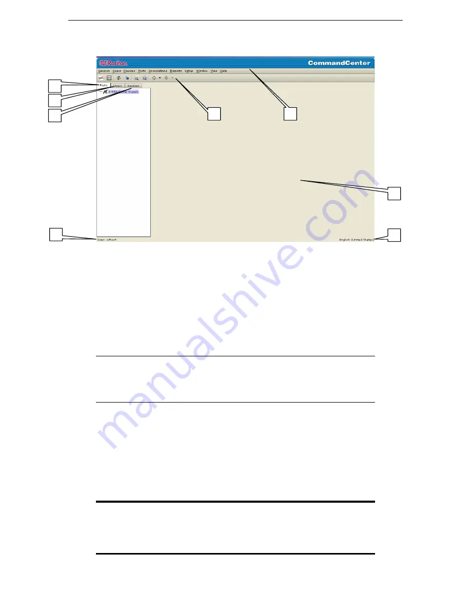
CommandCenter Window Components 


1.


Ports Selection tab: Click on the Ports tab to display all known target Ports in a Ports tree view. Click 
on the + and - signs to expand or collapse the tree. 

2.


Users Selection tab: Click on the Users tab to display all registered Users and Groups in a Users tree 
view. Click on the + and - signs to expand or collapse the tree. 

3.


Devices Selection tab: Click on the Devices tab to display all known Raritan devices in a Devices tree 
view. Different device types have different icons. Click on the + and - signs to expand or collapse the 
tree. 

4.


Quick Commands toolbar: This toolbar offers some shortcut buttons for executing common commands 
rapidly.  

Note: The Quick Commands toolbar has been upgraded in CC v2.1 and higher to include 
“Back” and “Forward” buttons, the left and right-pointing arrows. Please use these as 
you would use the Back and Forward commands in your Internet browser. The Back 

Å


arrow button will return you to the last screen you viewed, and the Forward 

Æ

 button 

moves you forward to the next screen you viewed, after you have used the Back command. 

5.


Operation and Configuration menu bar: These drop down menus offer commands to operate and 
configure CommandCenter. 

Please Note

: You can also execute some of these commands by right-

clicking on the icons in the Ports/Users/Devices tree view.  

6.


Main Display area: The commands you select from the menu bar and/or the tool bar will display in this 
main area. Displays here are referred to as ‘screens’ and screens may be broken down into ‘panels.’ 

7.


User ID: Identification of current logged-in user. 

8.


Language Information: Indication of which language version of CommandCenter you are currently 
using. 

Important: This user guide is written to address CommandCenter 
Administrators in the second person. Any phrase that addresses the 
reader as “you” is referring to users with Administrator permissions. 
Administrators can assign subsets of Administrator permissions to other 
users. 

3


4


Summary of Contents for COMMANDCENTER 2.20 -

Page 1: ...Lane 235 Pao Chiao Rd Hsin Tien Taipei Hsien Taiwan ROC Tel 886 2 8919 1333 Fax 886 2 8919 1338 E mail sales asia raritan com http www raritan com tw Raritan Computer France 120 Rue Jean Jaures 93200...

Page 2: ......

Page 3: ...reau of Export Administration at www bxa doc gov CC Version 2 2 CommandCenter V2 2 fully supports the Dominion family the Dominion SX family IP Reach M1 and IP Reach TR361 CommandCenter V2 2 offers pa...

Page 4: ...This page intentionally left blank...

Page 5: ...ing CommandCenter Manager Components 16 Configurable Parameters 16 User Manager 16 Add User 17 Edit User 18 Change User Password 18 Change Own Password 19 Delete User 19 Logoff User s 20 Bulk Copy 21...

Page 6: ...Serial Port 60 Edit a KVM Port 61 View Ports 62 Regular View 62 Custom View 63 Add Custom View 64 Edit Custom View 64 Delete Custom View 65 Port Power Manager 66 Port Group Manager 67 Add Port Group...

Page 7: ...t 108 Audit Trail Report 109 Error Log Report 111 Ping Report 113 Accessed Devices Report 114 Group Data Report 116 User Data Report 117 Users In Groups Report 118 Query Port Report 119 Refresh Comman...

Page 8: ...p Screen 24 Figure 25 Edit User Group Policies Screen 25 Figure 26 Group Delete User Group Screen 26 Figure 27 Assign Users in Group Screen 26 Figure 28 Add Device Selection Screen 28 Figure 29 Add De...

Page 9: ...e 75 Raritan Remote Client Window 57 Figure 76 HP s Remote Console Applet 58 Figure 77 Port Power Manager for iLO RILO targets 59 Figure 78 Active Ports Report 59 Figure 79 Edit Serial Port Screen 60...

Page 10: ...oth 95 Figure 129 Configuration Settings Device Settings Screen 96 Figure 130 Configuration Settings Device Settings Screen 97 Figure 131 Cluster Configuration Screen 99 Figure 132 Cluster Configurati...

Page 11: ...ndCenter Screen 121 Figure 160 Restart Screen 122 Figure 161 Info Window 122 Figure 162 Shutdown CommandCenter Screen 123 Figure 163 Logout Window 124 Figure 164 Exit Window 124 Figure 165 Association...

Page 12: ......

Page 13: ...to the IP network and presenting the serial console and KVM ports of all the target devices within the managed network Product Photos Figure 1 CommandCenter Figure 2 CommandCenter rear panel Product F...

Page 14: ...customizable views of all devices connected to CommandCenter supports automatic and manual device discovery Simplifies administration device upgrade reset diagnosis ping auto discover edit delete firm...

Page 15: ...onalization language keyboard scope of support documentation available in French German Japanese Traditional Chinese Simplified Chinese and Korean Package Contents CommandCenter is a fully configured...

Page 16: ...4 COMMANDCENTER USER GUIDE...

Page 17: ...nit Connect the other end of the cable to the network 2 Attach the included AC power cord to the Primary port on the rear panel of the CommandCenter unit Plug the other end or the cord into an AC powe...

Page 18: ...a password change will be rejected unless it meets the following criteria Passwords must be at least six characters long Passwords must contain at least one alphabetical character and one non alphabet...

Page 19: ...Paragon II System Controller as well as HP iLO RILO servers 1 Ensure that the device being added to the CommandCenter is already installed on the network Important Make certain no other users are log...

Page 20: ...dd Device 6 Type the new device name in the Device name field 7 Type the IP Address or Hostname of the new device in the Device IP or Hostname field 8 The TCP port number value will be populated autom...

Page 21: ...ommands in your Internet browser The Back arrow button will return you to the last screen you viewed and the Forward button moves you forward to the next screen you viewed after you have used the Back...

Page 22: ...10 COMMANDCENTER USER GUIDE...

Page 23: ...ugh a standalone client Install the executable from the included CD and run this instead of using the browser based applet This executable functions exactly like the downloaded applet Through SSH Plea...

Page 24: ...t allows you to connect to CommandCenter devices by launching a Java application instead of running an applet through a Web browser 1 Install the standalone CommandCenter client located on the include...

Page 25: ...s the complete keyboard video and mouse KVM of the remote target system through the CommandCenter CommandCenter can also interface with HP servers that have iLO or RILO access capabilities In this cas...

Page 26: ...t exit CommandCenter close the browser re launch the browser and connect to the CommandCenter again For additional details about RaritanConsole operation please refer to Raritan s RaritanConsole User...

Page 27: ...s associated with ports Figure 13 CommandCenter Application Window The CommandCenter menu bar displays all operations and configuration commands Active commands are based upon the privileges of the us...

Page 28: ...rmissions and devices they can manage please see the section User Manager in this chapter for additional information Establish the appropriate security and authentication policies Only an Administrato...

Page 29: ...eded 7 Check the Login Enabled check box to authenticate against the system if not user cannot enter the system 8 Check the Force Change Password on Next Login check box if you want this user to be fo...

Page 30: ...r Force Change Password Periodically 5 Click OK to submit the changes or Cancel to exit without saving An Updated Successfully message confirms the edits were submitted 6 Repeat steps 1 through 5 to e...

Page 31: ...ange your password or Cancel to exit without saving A User Profile Updated Successfully message confirms that your password has been changed 6 Repeat steps 1 through 4 to change your password whenever...

Page 32: ...e Users tree Note To select more than one user hold the CTRL key and click on additional users 2 On the Users menu click Logoff User s The Logoff Users screen appears Figure 19 Logoff Users Screen 3 C...

Page 33: ...lick on the name s and click Delete to move them back to the All Users list 6 Click OK to copy user properties or Cancel to exit without copying A User Copied Successfully message confirms that the us...

Page 34: ...removes a user from a specific group but not from the system If a user is not assigned to any other group that user is moved to Users Not In Group a non specific category shown at the base of the Use...

Page 35: ...as to be assigned the Device and Port Management feature To view other events that occur in the system those privileges must be selected upon Adding or Editing a User Group This chapter explains how t...

Page 36: ...e Users menu click Edit User Group The Edit User Group screen appears Figure 24 Edit User Group Screen 3 Type a new group name in the User Group Name field 4 Type a new description in the Description...

Page 37: ...screen appears Figure 25 Edit User Group Policies Screen 3 Click on a line item in the Policies list under the All Policies panel that you wish to assign to the group Scroll up or down to view all po...

Page 38: ...p has been deleted 4 Repeat steps 1 through 3 to delete other groups Assign Users to Group Use this command to assign users who are members of one group to a different group Users can be members of mo...

Page 39: ...n KVM Serial and Power devices have different icons in the Devices tree In addition availability status of each device also has a different icon For a description of what the icons represent please se...

Page 40: ...ce The Add Device selection screen appears Figure 28 Add Device Selection Screen 3 Click on the Device Type drop down arrow and select a type of device from the list 4 Click Next to proceed The Add De...

Page 41: ...ostname field 7 The TCP port number value will be populated automatically based on the device type 8 Type a description or location of the new device In the Description field 9 Type the name used to l...

Page 42: ...en 3 Type the new device properties in the appropriate fields on this screen up to and including selecting different or new Category and Element properties from the Device Association panel 4 Click OK...

Page 43: ...ice to the Selected Devices list 5 To remove a device from the Selected Devices list select the device and click Delete 6 Click OK to bulk copy or Cancel to exit without copying A Device Copied Succes...

Page 44: ...the window without restarting A Device Configuration Restored Successfully message confirms that all user and system configuration data has been restored 6 Repeat step 1 through 5 to restore other dev...

Page 45: ...raded 6 Repeat steps 1 through 5 to upgrade other devices Ping Device You can ping a device to determine if the device is available in your network 1 Click on the Devices tab and select a device from...

Page 46: ...ng a device have it continue with its normal activity by commanding it to resume 1 Click on the Devices tab and select the paused device from the Devices tree 2 On the Devices menu click Device Manage...

Page 47: ...more details on adding Categories to CommandCenter 1 Click on the Devices tab 2 On the Devices menu click Change View and then click Custom View The Custom View screen appears Figure 42 Custom View Sc...

Page 48: ...lect the detail and click the Delete button in the Custom User Details panel 7 Click Update to update the custom view A Custom View Updated Successfully message confirms that the custom view has been...

Page 49: ...ct the selected custom view 9 Click Close to close the Custom View screen 10 Repeat steps 1 through 9 to edit other custom views Delete Custom View 1 Click on the Devices Tab 2 On the Devices menu cli...

Page 50: ...Devices tab and select a device from the Devices tree 2 On the Devices menu click Topological View The Topological View for the selected device appears Figure 47 Topological View Screen 3 Navigate th...

Page 51: ...guration please see Raritan s Paragon Manager Paragon II System Controller User Manual After adding your Paragon System device the Paragon System includes the PIISC device connected UMT units and conn...

Page 52: ...ter it appears in the Devices tree Right click on the device icon in the Devices tree and select Remote User Station Admin The Remote User Station Admin screen appears listing all connected IP Reach a...

Page 53: ...the Devices menu click Device Power Manager The Device Power Manager screen appears Figure 52 Device Power Manager Screen 2 The outlets will be listed in the Outlets Status panel You may have to scro...

Page 54: ...already connected 1 On the Devices menu click Discover Raritan Devices The Discover Raritan Devices screen appears Figure 53 Discover Raritan Devices Screen 2 Click on the Devices Type drop down arrow...

Page 55: ...t were created specifically for CommandCenter in the device in the Username and Password fields to allow CommandCenter to authenticate the device when communicating with it in the future Select a Cate...

Page 56: ...ps Manager and then click Device Group Manager The Device Group Manager screen appears Figure 56 Device Groups Manager Screen 2 Click Add in the Groups panel The Add Device Group window appears Figure...

Page 57: ...own arrow and select the group to be edited from the list Click Edit and the Edit Device Group window appears Figure 59 Edit Device Group Window 3 Type the new name for the device group in the Enter N...

Page 58: ...Repeat steps 1 through 4 to delete other devices Add Device Rule After adding a device group apply one or more rules to the group so that devices can be grouped by matching parameters and you have a n...

Page 59: ...screen 6 Click Update to update the device group The new rule is associated with this device group from now on and any new devices will also comply with rules assigned to this device group 7 Click Clo...

Page 60: ...anager screen appears Figure 64 Device Groups Manager Screen 2 Select a rule to be deleted from the rule table and click Delete Rule The Delete Rule window appears Figure 65 Delete Rule Window 3 Click...

Page 61: ...ware support When you click on the Ports tab the Ports tree displays information about the Ports connected with CommandCenter For easier identification different ports have different icons in the tree...

Page 62: ...k Configure Ports The Configure Ports screen appears Figure 66 Configure Ports Screen 3 Click the Configure button that corresponds to the serial port line item you wish to configure The Configure Ser...

Page 63: ...box to enable flow control 11 Select the associated category and element from the Device Associations table 12 Click OK to configure the serial port or Cancel to exit without configuring A Port Creat...

Page 64: ...reen 4 Type a port name in the Port Name field 5 Click on the Application Name drop down arrow and select name 6 Select the associated category and element from the Device Associations table 7 Click O...

Page 65: ...and then click Configure Ports The Configure Ports screen appears Figure 70 Configure Ports Screen 3 Click the Configure button that corresponds to the outlet port line item you wish to configure A C...

Page 66: ...to remove the port entry from the Ports tree and Cancel all accessibility of the remote target device 1 Click on the Ports tab and select a port to be deleted 2 On the Devices menu click Port Manager...

Page 67: ...orts list select the port name s that will be adopting the profile of the port listed in the Port Name field above 4 Click Add to move port name s to the Selected Ports list 5 To remove any port names...

Page 68: ...ick on the Ports tab and select a serial port to connect to and manage 2 On the Ports menu click Connect Port 3 The Raritan Remote Client or JRRC application will launch in a new window Use the applic...

Page 69: ...window will inform you of connection status Once a connection is established RC JRRC opens in a new window Figure 75 Raritan Remote Client Window 4 When you are finished using RRC to manage the port...

Page 70: ...the Ports menu click Connect Port 3 A new java applet HP s Remote Console will launch once the applet loads you have KVM access to the iLO RILO enabled server Figure 76 HP s Remote Console Applet 4 W...

Page 71: ...he On or Off radio buttons for each outlet to power ON or power OFF the target 5 Click Recycle to restart the device connected to the target 6 Click Close to close the Port Power Manager screen Discon...

Page 72: ...down arrow and select a new rate 6 Click on the Parity Data Bits drop down arrow and select a new value 7 Click on the Parity Check check box to enable or disable 8 Click on the Recv Xmit Pace check...

Page 73: ...Port Screen 3 Type a new port name in the Port Name field 4 Click on the Application Name drop down arrow and select an application from the list 5 Select a new category and element from the Device A...

Page 74: ...ree grouped in default view you can change the regular view by assigning new criteria to a custom view see next section 1 Click on the Ports tab 2 On the Ports menu click Change View and then click Re...

Page 75: ...ctions 1 Click on the Ports tab 2 On the Ports menu click Change View and then click Custom View The Custom View screen appears Figure 82 Custom View Screen 3 To customize your view click on the Name...

Page 76: ...select the detail and click the Delete button in the Custom User Details panel 7 Click Update to update the custom view A Custom View Updated Successfully message confirms that the custom view has be...

Page 77: ...ces tree to reflect the selected custom view 9 Click Close to close the Custom View screen 10 Repeat steps 1 through 9 to edit other custom views Delete Custom View 1 Click on the Ports tab 2 On the P...

Page 78: ...Power Manager The Power Port Management screen appears Figure 86 Port Power Management Screen 3 Click the On option button to power ON the port 4 Click the Off option button to power OFF the port 5 C...

Page 79: ...igure 87 Port Groups Manager Screen 2 Click Add in the Group panel to add a new group The Add Port Group window appears Figure 88 Add Port Group Window 3 Type the name for the new Port Group in the En...

Page 80: ...or Cancel to close the window 5 Click Close to close the Port Groups Manager screen 6 Repeat steps 1 through 5 to edit other port groups Delete Port Group 1 On the Associations menu click Groups Manag...

Page 81: ...ve the elements San Jose San Francisco and New York associated with it and so on Once the tree view is customized using these attributes you can easily find for example all Firewall devices located in...

Page 82: ...ons menu click Association Manager The Association Manager screen appears 2 Click on the Category Name drop down arrow and select the category to be edited 3 Click Edit in the Category panel of the sc...

Page 83: ...r screen appears 2 Click on the Category Name drop down arrow and select the category to be deleted 3 Click Delete in the Category panel of the screen to delete the category The Delete Category window...

Page 84: ...to add other elements Edit Element 1 On the Associations menu click Association Manager The Association Manager screen appears 2 Select the element to be edited from the Element For Category list and...

Page 85: ...Category list and click Delete in the Elements For Category panel The Delete Element window appears Figure 98 Delete Element Window 3 Click Yes to delete the element or No to close the window The ele...

Page 86: ...dd the new policy or Cancel to close the window If you clicked OK the new policy name appears in the Name field 5 Click on the Device Group drop down arrow and select a device group 6 Click on the Por...

Page 87: ...lick on the Name drop down arrow to select a policy to edit Click Edit to edit the policy The Edit Appliance Policy screen appears Figure 102 Edit Appliance Policy Window 3 Type a new name for the pol...

Page 88: ...icy to be deleted Click Delete to delete the policy The Delete Appliance Policy window appears Figure 104 Delete Appliance Policy Window 3 Click Yes to delete the policy or No to close the window 4 Cl...

Page 89: ...pplications to different ports in order to access them individually as needed 1 On the Setup menu click Application Manager The Application Manager screen appears Figure 105 Application Manager Screen...

Page 90: ...cation Manager screen Note Once the application has been loaded into CommandCenter and assigned to a port verify that the application is operational Edit Application Use this command to modify an appl...

Page 91: ...k on the Application Name drop down arrow and select the application to be deleted 3 Click the Delete button in the Applications panel to delete the application The Delete Application window appears F...

Page 92: ...are name will appear in the Firmware Name field 4 Click Close to close the Firmware Manager screen Delete Firmware 1 On the Setup menu click Firmware Manager The Firmware Manager screen appears 2 Clic...

Page 93: ...o change their passwords on the remote server There is no password to be changed on the CommandCenter Active Directory servers may be used for remote authorization in addition to remote authentication...

Page 94: ...ncrypted connections to CommandCenter 3 Check the Force Strong Password Check check box if needed 4 The modules in the table represent the multiple authentication options available in CommandCenter Se...

Page 95: ...e the first LDAP server 3 Check Use Active Directory if this server is an Active Directory server 4 Type the IP address and port value of the LDAP server in the IP Address and Port fields 5 Check Secu...

Page 96: ...ption or as plain text 12 Click on the Default Digest drop down arrow and select the default encryption of user passwords 13 Type the user attribute and group membership attribute parameters in the Us...

Page 97: ...nd password entered at login to the LDAP server for authentication If Use Bind is not checked CommandCenter will search the LDAP server for the user name and if found will retrieve the LDAP object and...

Page 98: ...Manager TACACS Screen 2 Type the server name in the Server Name field 3 Type the port number in the Port Number field 4 Type the authentication port in the Authentication Port field 5 Type the shared...

Page 99: ...ab Figure 118 Security Manager RADIUS Screen 2 Type the server name in the Server Name field 3 Type the port number in the Port Number field 4 Type the shared key into the Shared Key and Shared Key Co...

Page 100: ...ey panel Copy the text of the Certificate and Private Key and submit it by clicking Export b Click on the Import Pasted Certificate and Private Key option button You can paste Certificate and Private...

Page 101: ...s Type the data needed for the self signed Certificate into the fields then click OK to generate the certificate or Cancel to exit that window If generated the Certificate and Private Key will appear...

Page 102: ...a new item to the list type a starting IP in the Starting IP field and an ending IP in the Ending IP field Select a Group to apply this range to and under Action select whether they are allowed or de...

Page 103: ...he Domain Suffix field for example a Raritan Administrator would type raritan com 5 Click appropriate option button for either Primary Backup Mode or Active Active Mode for security reasons you may wa...

Page 104: ...to close the Configuration Manager screen Note These address changes will not be applied to the system until CommandCenter is rebooted Inactivity Timer Configuration Use this screen to time out inact...

Page 105: ...n Manager When the Configuration Manager screen appears click on the Time Date tab Figure 125 Configuration Manager Time Date Screen a To set the date and time Manually To set the Date click on the dr...

Page 106: ...with that device Direct Mode or to route all the data through your CommandCenter unit Proxy Mode While Proxy Mode increases the bandwidth load on your CommandCenter you only need to keep the CommandCe...

Page 107: ...to connect to directly i Type the device s IP Address in the Net Address field at the base of the screen ii Type the devices s net mask in the Net Mask field iii Click the Add button to add the Net A...

Page 108: ...Default Port value Type the new Default Port value 3 To update device timeout duration double click on the Heartbeat sec value at the base of the screen Type new timeout duration for this device Figur...

Page 109: ...le the SNMP feature of CommandCenter 3 Click on the radio button before SNMP V1 or SNMP V2 depending on which protocol your SNMP managers use 4 The Read Only Community and Read Write Community will po...

Page 110: ...server to the list of configured managers To remove a manager from the list select the manager and click Remove There is no limit to the number of managers that can be set in this list 8 When all SNMP...

Page 111: ...umes all Primary node functionality This requires initialization of the CommandCenter application and user sessions all existing sessions originating on the Primary CommandCenter node will terminate T...

Page 112: ...often CommandCenter should check its connection with the other node Note Setting a low Time Interval will increase the network traffic generated by heartbeat checks Also clusters with nodes located f...

Page 113: ...ode s version 3 Enter an administrator username and password for that unit in the Backup Username and Password field Figure 134 Selecting Secondary Node from Cluster Configuration table 4 Click Join B...

Page 114: ...y detects the unit at the specified address it will be added to the table above 3 Select the newly added CommandCenter and set it as a Secondary Node as described in steps 2 7 in the Set Secondary Com...

Page 115: ...he designation of Primary Node Remove Cluster is only available when no backup nodes exist 3 Click Close to exit the Cluster Configuration screen To Recover a Failed CommandCenter Node When a node fai...

Page 116: ...ter screen appears click OK to reset your CommandCenter unit Figure 139 Reset CommandCenter Screen 2 A success message will appear to confirm the reset Backup CommandCenter 1 On the Setup menu click B...

Page 117: ...Uploading Backup Files You can also save and load CommandCenter backups to and from your local PC using the Restore CommandCenter screen 1 Click on the backup you wish to save to your PC and then cli...

Page 118: ...the cell name indicating how the report is sorted The column width in all reports can be sized by resting your mouse pointer on the column divider in the header row until it becomes a double headed ar...

Page 119: ...ys ports that are currently in use You can view or disconnect ports from this report 1 On the Reports menu click Active Ports The Active Ports report is generated Figure 145 Active Ports Report 2 To d...

Page 120: ...play a list of possible devices for which to run the report Select one and click Apply to run the report 3 Press Refresh to update the query and generate a new report Please note that the report may t...

Page 121: ...il The Audit Trail screen appears Figure 147 Audit Trail Screen 2 Select the date range for the report by either typing the date and time in the Start Date and End Date fields using the format yyyy mm...

Page 122: ...designated time period Figure 148 Audit Trail Report 7 Click Manage Report Data to save or print the report Click Save to save the report to a location of your choice or Print to print the report Clic...

Page 123: ...or Log screen appears Figure 149 Error Log Screen 2 Select the date range for the report by either typing the date and time in the Start Date and End Date fields using the format yyyy mm dd hh mm ss o...

Page 124: ...designated time period Figure 150 Error Log Report 7 Click Manage Report Data to save or print the report Click Save to save the report to a location of your choice or Print to print the report Click...

Page 125: ...s on your system and will supply information that could be useful in case troubleshooting is necessary 1 On the Reports menu click Ping Report The Ping Report is generated Figure 151 Ping Report 2 Cli...

Page 126: ...ces screen appears Figure 152 Accessed Devices Screen 2 Select the date range for the report by either typing the date and time in the Start Date and End Date fields using the format yyyy mm dd hh mm...

Page 127: ...eport Figure 153 Accessed Devices Report 6 The Accessed Devices report is generated displaying data about devices accessed during the designated time period 7 Click Clear to clear the contents of the...

Page 128: ...en 1 On the Reports menu click Group Data The Groups report is generated Use the scroll bars to scroll through the lists and view all entries Figure 154 Groups Report 2 Click any of the Manage Report...

Page 129: ...ess to CommandCenter The Password Expiration shows that user s password expiration period in days 1 On the Reports menu click User Data The All Users Data report is generated Use the scroll bar to scr...

Page 130: ...rs In Groups The Users In Groups report is generated Use the scroll bar to scroll through the list and view all entries Figure 156 Users In Groups Report 2 Click Manage Report Data to save or print th...

Page 131: ...according to port status 1 On the Reports menu click Query Port The Query Port screen appears Figure 157 Query Port Report 2 Click on the checkbox to customize the port information you want to see on...

Page 132: ...ed in the system until the database is updated If you are logged in while another user is updating the database you will not see these changes unless you refresh your screen or log out of CommandCente...

Page 133: ...st remove the cluster first and upgrade each node separately 1 On the Setup menu click Upgrade CommandCenter The Upgrade CommandCenter screen appears Figure 159 Upgrade CommandCenter Screen 2 If you a...

Page 134: ...s a brief time period to finish their tasks in CommandCenter or tell them why you are restarting the system All users will be disconnected when you restart CommandCenter 4 Type how much time in second...

Page 135: ...mmandCenter 4 Type how much time in seconds should pass before CommandCenter shuts down in the Shutdown after sec field 5 Click OK to shut down CommandCenter or Cancel to exit the screen without shutt...

Page 136: ...ther user has made changes while you were logged in log off from CommandCenter entirely then log in again 1 On the Session menu click Logout The Logout window appears Figure 163 Logout Window 2 Click...

Page 137: ...each axis X Y Z Shock N A NON OPERATING Temperature 0 deg C 50 deg C 3232 deg F 12232 deg F Humidity 10 90 RH Altitude Operate properly at any altitude between 0 to 10 000 feet storage 40 000 feet es...

Page 138: ...126 COMMANDCENTER USER GUIDE...

Page 139: ...ntified Add Ports with Category Element clearly identified 2 Create Group s Add User s 3 Add Device Group with rule based on Category Element 4 Add Port Group with rule based on Category Element 5 Add...

Page 140: ...128 COMMANDCENTER USER GUIDE...

Page 141: ...scover Raritan devices Change Port View Users are able to customize port view Edit Port Users are able to modify port name and parameters Active Ports Users are able to view active users Asset Managem...

Page 142: ...e to modify user name and parameters Change User Password Users are able to change other user password Delete User Users are able to delete user from the system Logoff User Users are able to logoff us...

Page 143: ...plet does not load check your Web browser settings In IE on the Tools menu click Internet Options and click on the Advanced tab Ensure Java Sun is enabled Open Java Plug in in your Control Panel click...

Page 144: ...132 COMMANDCENTER USER GUIDE...

Page 145: ...information No testing has been done in this area Is the status of CommandCenter limited by the status of the devices which it proxies No Because CommandCenter software resides on a dedicated server e...

Page 146: ...center model uses Paragon to scale to thousands of systems in a single data center This is the most effective and cost efficient way to scale a single location It also supports the network model with...

Page 147: ...n they finish an operation As Raritan has Root access to server this may potentially cause issue with Government bodies Can customers also have root access or can Raritan provide a method of auditabil...

Page 148: ...ouble shooting and diagnosis of system and network problems How do you recommend the issue of CIMs being moved swapped at the physical level with changes to the logical database Each CIM includes a se...

Page 149: ...to view them all A user is able to open many screens each one corresponding to one edge port but the user is restricted on the KVM side by the actual capacity of KVM over IP channels to be able to acc...

Page 150: ...138 COMMANDCENTER USER GUIDE 255 80 3100...

Reviews: