background image

Trying out the instrument

R&S

®

SMCV100B

57

Getting Started 1432.7046.02 ─ 04

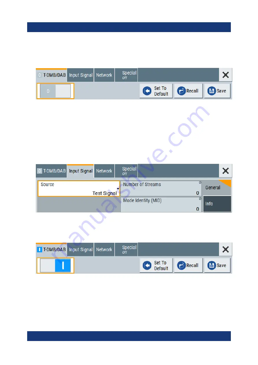
2. In the block diagram, select "Baseband > T-DMB/DAB".

The "T-DMB/DAB" dialog appears and displays the general settings provided
for the digital standard.

As in the user interfaces of all broadcast standards, the "T-DMB/DAB" dialog
is divided into several tabs. The "T-DMB/DAB" tab comprises the primary set-
tings of the standard.
Also, the functions for storing and recalling settings and provides access to
further functions and dialogs. The more complex the digital standard itself is,
the more comprehensive the further dialog and tab structure.

3. In the "Input Signal" tab, select "Source > Test Signal".

The test signal is a signal with audio content.

Tip: 

On the front panel, press the Help key to retrieve detailed information on

the current settings and on the contents of the predefined files.

4. In the "T-DMB/DAB" tab, select "State > On".

5. On the "Status Bar", set "Frequency" and "Level" of the DAB test signal:

a) Tap the "Frequency" field, to enter the center frequency, for example

174.928


MHz

.

b) Tap the "Level" field, to enter the RMS level, for example 

20.00


dBm

.

Generating a DAB signal

Summary of Contents for SMCV100BP1

Page 1: ...R S SMCV100B Vector Signal Generator Getting Started 1432704602 Version 04 P 2...

Page 2: ...ww rohde schwarz com Subject to change data without tolerance limits is not binding R S is a registered trademark of Rohde Schwarz GmbH Co KG Trade names are trademarks of the owners 1432 7046 02 Vers...

Page 3: ...3 Service manual 13 2 4 Instrument security procedures 13 2 5 Printed safety instructions 13 2 6 Data sheets and brochures 13 2 7 Release notes and open source acknowledgment OSA 14 2 8 Application no...

Page 4: ...tally modulated signal 40 6 3 Triggering the instrument with an external signal 42 6 4 Enabling and configuring a marker signal 48 6 5 Verifying the generated signal with the graphics display 49 6 6 S...

Page 5: ...rol 64 8 1 Possible ways to operate the instrument 64 8 2 Means of manual interaction 65 8 3 Understanding the display information 65 8 4 Accessing the functionality 71 8 5 Entering data 72 8 6 Gettin...

Page 6: ...Contents R S SMCV100B 6 Getting Started 1432 7046 02 04...

Page 7: ...same information is provided in many languages as printed Safety Instructions The printed Safety Instructions are delivered with the product Throughout the documentation safety instructions are provid...

Page 8: ...ied you can operate the product up to an altitude of 2000 m above sea level The product is suitable for pollution degree 2 environ ments where nonconductive contamination can occur For more informatio...

Page 9: ...act cables and route them carefully so that they cannot be dam aged Check the power cables regularly to ensure that they are undamaged Also ensure that nobody can trip over loose cables If the product...

Page 10: ...Connecting to power on page 9 Product and environment safety see Table 1 1 Identification of the product see the serial number on the rear panel Table 1 1 Labels regarding R S SMCV100B and environment...

Page 11: ...7046 02 04 CAUTION Potentially hazardous situation Could result in minor or moderate injury if not avoided NOTICE Potential risks of damage Could result in damage to the supported product or to other...

Page 12: ...software options are provided for download Base unit manual Contains the description of all instrument modes and functions It also pro vides an introduction to remote control a complete description o...

Page 13: ...ocedures Deals with security issues when working with the R S SMCV100B in secure areas It is available for download on the Internet 2 5 Printed safety instructions Provides safety information in many...

Page 14: ...cribe the firmware installation The open source acknowledgment document provides verbatim license texts of the used open source software See www rohde schwarz com firmware smcv100b 2 8 Application not...

Page 15: ...with internal broadcast real time coder Custom Digital Modulation and internal baseband signal generation with ARB Support of various broadcast standards covering multiple fields of application Terres...

Page 16: ...al Use it to protect the control elements and connectors when transporting or shipping the R S SMCV100B later See also chapter Transporting in the user manual 3 Using the delivery notes check the equi...

Page 17: ...e for class B environments If class A equipment causes radio disturbances take appropriate measures to eliminate them 4 4 Setting up the R S SMCV100B See also Setting up the product on page 8 Intended...

Page 18: ...nimum distance of 10 cm between the fan openings of the prod uct and any object in the vicinity Do not place the product next to heat generating equipment such as radia tors or other products 4 4 2 Mo...

Page 19: ...g the R S SMCV100B on a bench top again unmount the adapter kit from the R S SMCV100B Follow the instructions provided with the adapter kit 4 5 Considerations for test setup Cable selection and electr...

Page 20: ...6 Signal input and output levels Information on signal levels is provided in the data sheet Keep the signal levels within the specified ranges to avoid damage to the R S SMCV100B and connec ted device...

Page 21: ...configured to use DHCP dynamic host config uration protocol and no static IP address is configured If switched on and connected to the LAN the R S SMCV100B displays the address information on the scre...

Page 22: ...nect the USB storage device to a USB type A connector When connecting to the front panel connect the USB storage device directly without connecting cable Connecting cables can cause electromagnetic ra...

Page 23: ...echanically compatible See the application note 1MA99 for information on how to handle and main tain the RF port to minimize measurement deviations and ensure its longevity 2 NOTICE Risk of instrument...

Page 24: ...utput level without a load connected to the instrument the reverse power can exceed a limit forcing the R S SMCV100B to switch off the RF output Connect a load with sufficient return loss as given in...

Page 25: ...e EMI on page 19 2 Hold the QSFP plug of the cable by its panes 3 Turn the QSFP cable so that the release tab shows upwards 4 Insert and push the QSFP plug into the QSFP cage To disconnect from Dig IQ...

Page 26: ...an RJ 45 cable See Cable selection and electromagnetic interference EMI on page 19 4 3 3a 1 2 2 Figure 4 2 Connecting to the IP Data interface 1 RJ 45 cable and plug 2 Axis of connection 3 SFP to RJ...

Page 27: ...nterface Use the IP Data interface as input of external coding IP data for broadcast base band signals See also chapter Local IP Data Network Settings in the corresponding broad cast standard user man...

Page 28: ...n addition to automatic monitoring you can per form maintenance tasks See Chapter Querying Error Messages in the user manual Chapter Performing Maintenance Tasks in the user manual To shut down the pr...

Page 29: ...t The meanings of the labels on the R S SMCV100B are described in Chapter 1 2 Labels on R S SMCV100B on page 10 5 1 Front panel tour This section provides an overview of the control elements and conne...

Page 30: ...of the instrument 2 3 1 Figure 5 2 Touchscreen elements 1 Status bar frequency and level display 2 Block diagram 3 Taskbar softkey bar Any user interface elements that react to a click by a mouse poin...

Page 31: ...the R S SMCV100B to return to a defined instrument state and provide information on the instrument and assistance For more information refer to chapter General Instrument Functions in the user manual...

Page 32: ...Description Esc key Closes all kinds of dialog boxes if the edit mode is not active Quits the edit mode if the edit mode is active In dialog boxes that contain a Cancel button it activates that button...

Page 33: ...USB universal serial bus 2 0 connector of type A host USB You can connect for example a keyboard a mouse or a USB memory stick Further USB connectors of type A are available on the rear panel How to...

Page 34: ...Ref In Ref Out page 36 5 2 1 Connectors AC power supply connector and switch Mains power switch for performing the following tasks Connecting the internal power supply to the power source Disconnecti...

Page 35: ...the required option For more information see data sheet Table 5 4 Overview of Dig IQ HS x interfaces and required options Interface Designation Required option Dig IQ HS 1 BB Input R S SMCVB K19 digit...

Page 36: ...ctor status green an input connector yellow an output connector red error no light gray the connector is not active blinking LED connection indication as a result of the Identify Connector function Se...

Page 37: ...u do not need any additional signal source More complex signal generation tasks however require an instrument equipped with additional options and or external signals Each task description lists its p...

Page 38: ...panel press the Preset key to start out in a defined instrument configuration 2 Set the frequency a On the Status Bar tap the Frequency field b On the on screen keypad enter 1 955 and press the GHz k...

Page 39: ...signal is output at the RF 50 connector at the front panel of the R S SMCV100B Connect RF 50 of the R S SMCV100B to a signal analyzer for example R S FSW to display the generated signal Figure 6 2 Sim...

Page 40: ...Option custom digital modulation R S SMCVB K199 The initial situation is not the instrument s preset state but rather the configuration described in Chapter 6 1 Generating an unmodulated carrier on pa...

Page 41: ...The instrument activates automatically I Q Mod uses the internal trigger and clock signals and generates a WCDMA 3GPP signal modulated with a QPSK 45 offset modulation Figure 6 3 Block diagram Genera...

Page 42: ...stom digital modulation R S SMCVB K199 As a rule whenever a test setup requires two or more devices provide them with a common reference frequency Some test setups require control of the signal genera...

Page 43: ...nstrument and the external trigger source See To connect the instrument and the external trigger source on page 46 To verify the current connector configuration The R S SMCV100B is equipped with multi...

Page 44: ...6 5 Signal mapping to the global connectors The Global Connectors dialog displays the current connectors configuration The settings are configurable but in this example we use the default mapping 3 A...

Page 45: ...lso indicates the selected connector To reconfigure the trigger settings We assume that the instrument is configured as described in Chapter 6 2 Gen erating a digitally modulated signal on page 40 and...

Page 46: ...the input connector User 2 The Trigger Marker Clock status LEDs in the block diagram confirm that an external trigger signal is selected the signal generation is however stopped To connect the instrum...

Page 47: ...rigger source the DUT can also send for example a frame trigger signal to the R S SMCV100B The R S SMCV100B acts still as the signal source 2 Use suitable cables to connect to RF 50 and Ref In connect...

Page 48: ...tion as in Prerequisites on page 37 Option custom digital modulation R S SMCVB K199 This example extends further the configurations performed in Chapter 6 2 Gen erating a digitally modulated signal on...

Page 49: ...the spectra of the configured signals before you enable the RF output of the instrument The R S SMCV100B has a minimum configura tion as in Prerequisites on page 37 The R S SMCV100B provides a build i...

Page 50: ...the following Select Taskbar System Configuration Graphics On the Taskbar tap the wave icon The Graphics Configuration dialog opens To visualize the signal 1 In the Graphics Configuration dialog sele...

Page 51: ...can verify that Channel 0 graphic is visible in the table A new thumbnail minimized view indicating the active diagram appears in the Taskbar 4 Press the thumbnail graphic The graphic enlarges and th...

Page 52: ...pinching for magni fying images on your cellphone 6 In the Constellation Diagram dialog select Configure to return to the Graphics Configuration dialog Close the Graphics Configuration dialog This act...

Page 53: ...ent settings to a file To save the instrument settings to a file We assume a test configuration as described in Chapter 6 4 Enabling and con figuring a marker signal on page 48 1 Press the Save Rcl ke...

Page 54: ...er To load saved instrument settings You can restore the settings to the instrument at any time using the settings file 1 Press the Preset button to restore the default instrument settings 2 Press the...

Page 55: ...lues different to their preset values After loading saved instrument setting visualize all parameters that have been changed from their default state 1 In the block diagram open the context sensitive...

Page 56: ...T2 or ATSC3 0 to name a few This example uses the digital broadcast standard DAB You can access and interact with the instrument and experience the advantages provided by the additional options Prereq...

Page 57: ...s to further functions and dialogs The more complex the digital standard itself is the more comprehensive the further dialog and tab structure 3 In the Input Signal tab select Source Test Signal The t...

Page 58: ...On RF On The instrument generates a DAB test signal with the set frequency and level With these first steps you have gained an impression of the provided func tionality For a comprehensive descriptio...

Page 59: ...nd section of the R S SMCV100B is fully digital It contains the hardware for generating and processing I Q signals in realtime or generating signals with an arbitrary waveform generator 7 2 Signal flo...

Page 60: ...and the displayed set tings The Table 7 1 is an excerpt of the available options and lists only the options required to display a functional block in the block diagram The information assumes R S SMC...

Page 61: ...les for real time signal generation Custom Digital Modulation requires R S SMCVB K199 and an arbitrary waveform generator ARB The available digital standards Generation of digital signals in accordanc...

Page 62: ...al digital I Q signals are further processed in the baseband section The baseband offsets function The external and internal baseband signals can be shifted in frequency and phase The I Q Digital bloc...

Page 63: ...s point to RF frequency and level settings and the reference frequency user correction etc The list and sweep modes 7 9 Applications examples of the R S SMCV100B The R S SMCV100B can be optimally adap...

Page 64: ...and rotary knob or an optional mouse and or keyboard The following description shows how to operate the instrument manually Remote control Create programs to automatize repeating settings tests and me...

Page 65: ...keys and rotary knob The front panel provides nearly all functions and controls to operate the instru ment in the classic way without touchscreen Optional mouse and or keyboard These devices work lik...

Page 66: ...ftkey bar Status bar 66 Block diagram 67 Taskbar 68 Additional display characteristics 69 8 3 1 Status bar The status bar at the top of the screen indicates the RF frequency and the level of the outpu...

Page 67: ...ays the most common elements that can appear in the block diagram However it does not necessarily represent a useful configuration 1 11 Baseband domain digital RF domain analog 3 4 5 6 8 9 7 2 10 1 10...

Page 68: ...access to any number of associated actions to accomplish the task The On Off checkbox and the block label quickly activates the basic task 5 6 Graphics indicator Denotes that the signal is displayed...

Page 69: ...annel 5 Diagram more The diagram icon as shown in Figure 8 2 minimizes all dialogs indicated on the screen The block dia gram is in the foreground The More softkey indicates that more dialogs are open...

Page 70: ...ameters indicated in tab labels Most dialogs are divided into tabs with logically grouped parameters The tab label expresses the content and can also contain status indicators or the set value of a ke...

Page 71: ...s functions and settings can be accessed by selecting one of the following elements System and function keys on the front panel of the instrument Taskbar softkeys on the touchscreen Context sensitive...

Page 72: ...op a minimized dialog from the taskbar to the block diagram To select an option in a dialog box Tap the required option To select an option in a list If many options are available for example for the...

Page 73: ...e numeric keypad The units specified correspond to the units of the parameter 1 Enter the numeric value Tip For quick entry you can enter a value in exponential representation e g 1e7 for 10000000 2 T...

Page 74: ...Getting information and help In some dialog boxes graphics are included to explain the way a setting works For further information you can use the following sources Tooltips give the value range of t...

Page 75: ...s To open general help Press the yellow Help key on the front panel If a dialog box is opened the help topic for the current tab is shown Other wise the Contents page appears Navigating in the table o...

Page 76: ...y The corresponding help topic is displayed 8 7 Remote control In addition to working with the R S SMCV100B interactively located directly at the instrument it is also possible to operate and control...

Page 77: ...instrument Thus remote operation of the instrument is possible Instrument control from a remote computer To access the basic utility functions of the R S SMCV100B perform a right mouse click the block...

Page 78: ...duct contact our customer support center A team of highly qualified engineers provides support and works with you to find a solution to your query on any aspect of the operation program ming or applic...

Page 79: ...DVI D 34 High speed digital IQ 35 IP data 35 LAN 35 Ref In 36 Ref Out 36 RF 50 33 USB 33 35 USER 35 Context sensitive menu 69 Custom digital modulation 61 Customer support 78 D Data entry 72 Data shee...

Page 80: ...Trying out 54 M Manual interaction 65 Mounting in a rack 18 Mouse Usage 65 N Network Environment 20 Numeric data entry 72 Numeric parameters 73 O On screen keyboard 74 On screen keypad 69 Open source...

Page 81: ...bar see Taskbar 68 Software options 61 Standby Key 31 Status bar Display 66 Switching On or off 27 T Tab labels 69 Text entry 72 Tooltips Show 74 Touchscreen Compared with mouse 65 Overview 30 Usage 6...

Reviews: