background image

RABE

PAVOtronic

80

PAVO V140 / VHA 140

09.2011

16.0 Maintenance

16.1  Safety instructions - Maintenance and repair

  WARNING 


Risk of accident due to pinching or crushing while performing maintenance work. 

Turn off the engine of the tractor and take the key out of the ignition. 
Only perform work when the implement is in a safe condition and has been secured to 

prevent it from dropping and rolling away.  

Use all provided supports.
During all work, wear work gloves, the prescribed working clothing and protective equipment.
Always disconnect the power before starting any work on the electrical system.
Before performing welding work, disconnect all power connections to the tractor.
Secure the implement to prevent unauthorised start-up while such work is in progress.

  Risk of injury due to heavy components.

When handling heavy components, use suitable lifting devices or seek the assistance 

of a second person.


Maintenance

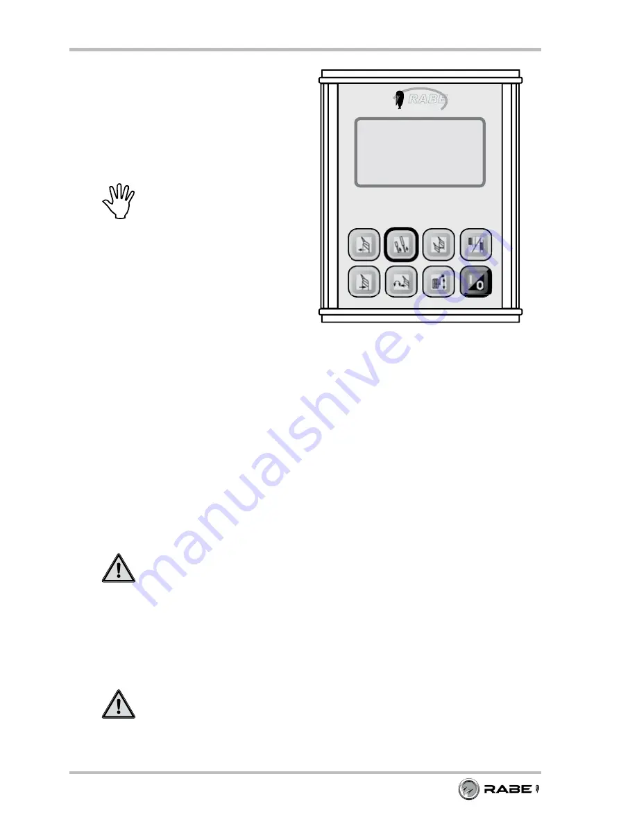
PAVOtronic terminal

PAVOtronic with a damp cloth, if 

necessary a mild household cleaner 

may be used in addition.

  NOtE


Store the PAVOtronic such that it is 

protected from moisture and cold. 

 Do not store the PavOtronic in 

the open.

Fig. 111:  PAVOtronic

Summary of Contents for Pavo V 140

Page 1: ...EN Operating Instructions Serial no Pavo V 140 PAVO VHA 140 with PAVOtronic Series 1...

Page 2: ...s publication in other media translations or use of extracts or parts are not permitted without the express permission of Gr goire Besson GmbH All rights reserved The contents of these operating instr...

Page 3: ...n to mean in the direction of travel This document was produced using the information with respect to equipment and operation which was known at the time of printing Changes due to technical improveme...

Page 4: ...PAVO V140 VHA 140 09 2011...

Page 5: ...symbols on the implement 17 2 0 Scope of delivery 19 2 1 Basic equipment 19 2 2 Additional equipment 19 3 0 Description of the implement 20 3 1 Functional description 20 3 2 Description of the assembl...

Page 6: ...overlap 37 9 3 Setting Pavotronic furrow on land work mode 38 9 4 Basic settings Ploughing in the FURROW 39 9 4 1 Operating information 39 9 4 2 Preparation 39 9 4 3 Switching on the Pavotronic 40 9...

Page 7: ...6 11 3 5 Changing the first plough body working width Ploughing in the furrow 67 11 3 6 Adjusting the working width of each plough body On land ploughing 68 11 3 7 Track setting of first plough body t...

Page 8: ...Setting the Language 89 17 6 Switching Valve monitoring on or off 90 18 0 Rectifying faults 90 19 0 Repair 91 19 1 Replacing the leg shear bolt 91 19 2 Replacing the skimmer shear bolt 92 19 3 Replaci...

Page 9: ...bol in this document Meaning Hazard warning Hazard warnings allude to risks which occur when using the implement The hazard warnings are arranged into different levels and are described with the signa...

Page 10: ...l times 1 6 Who may operate the implement Qualified persons only The implement may only be operated maintained or repaired by persons whose qualifications authorise them to do so and who are sufficien...

Page 11: ...l safety and accident prevention regulations Check the tractor and implement for operational and road safety prior to every start up Before first use re tighten all bolts to the specified torque All s...

Page 12: ...ate clearance around the implement Warning Risk of accident from the folding and unfolding of implement parts When folding and unfolding implement parts make sure that no persons are standing in the d...

Page 13: ...iginal spare parts Use suitable tools when looking for leakages Set down implements depressurise the system switch off the engine and remove the ignition key before commencing work on the hydraulic sy...

Page 14: ...diate vicinity The operator must not leave the operator s platform while the vehicle is in motion Risk of accident due to unsecured attachment components Secure all components of the attachment to pre...

Page 15: ...of the tractor and take the key out of the ignition Only perform work when the implement is in a safe condition and has been secured to prevent it from dropping and rolling away Use all provided supp...

Page 16: ...ous accidents Adjustment and repair work on brake systems may only be performed by individuals with the proper technical training or by service centres Risk of accident due to improperly carried out w...

Page 17: ...between the tractor and the implement when activating the external control for the three point linkage 9998 02 88 9998 02 88 Pay attention to the transport lock It is essential that the transport loc...

Page 18: ...18 PAVO V140 VHA 140 09 2011...

Page 19: ...ng form part of the implement delivery 1 Pavotronic electronic control with a control cable and b power supply 2 Suction holder for Pavotronic 3 Shear bolt M14 x 90 mm with self locking nut 6 pcs 4 M1...

Page 20: ...n 4 and 8 km h ensure a consistent precise ploughed surface The frame construction with 140x140 mm base frame and a hollow rotating axle with 150 mm diameter guarantee that the design is both robust a...

Page 21: ...cking the turning device c the rotation head for turning the plough with a hose grommet d bottom coupling point for coupling the tractor s bottom links e the receptacles for the hydraulic lines f the...

Page 22: ...used to set the working width of all plough bodies centrally 3 2 6 Plough bodies The plough bodies come in solid sheet metal or slatted designs Implement description Fig 7 Plough bodies Solid sheet m...

Page 23: ...3 2 9 Pick up arm additional equipment The pick up arm 2 which is attached to the front flange plate 1 of the frame has an adjustable slewing range This ensures that the pick up arms of the packer are...

Page 24: ...unit Selection of in the furrow or on land ploughing Neutral position Track setting Turn setting Working width Combination wheel working depth 3 3 Pavotronic electronic control Display Function butto...

Page 25: ...Rear power lift min lifting capacity T 8 5 9 5 10 5 Working width cm 26 55 26 55 26 55 L Length mm 5300 6150 7000 W Transport width mm 2300 2700 2950 H Transport height mm 1820 1820 1820 BD Bottom lin...

Page 26: ...ustment other settings Green 3 4 4 Required power connections Consumer Poles Voltage Power connection Lighting system 7 pole 12 VDC Acc to DIN ISO 1724 PAVOtronic electronic control 3 pole 12 VDC Acc...

Page 27: ...ment proceed with care and pay attention to balance The implement may only be lifted using the crane eyes 1 This ensures a high degree of safety when loading With cranes ensure that only suitable lift...

Page 28: ...Implement see Technical data Calculation the required ballasting of the tractor See Chapter 5 2 Check that the connection category of the tractor and implement is the same Tractor see tractor operati...

Page 29: ...the suction foot with the clamping lever a above the PAVOtronic 1 Insert the guides from the flange plate of the suction foot into the receptacles on the PAVOtronic and 2 Engage by sliding it along P...

Page 30: ...n easily accessible place in the tractor cab and 3 Fold down the clamping lever Fig 17 Securing the PAVOtronic Note In order to secure the suction holder to rough textured surfaces the supplied basepl...

Page 31: ...ongated hole in the tower and then place the anti twist device of the pin a over the bolt b Secure the pin with a washer and locking pin c Couple the top link 6 to the pin and lock During coupling mak...

Page 32: ...entional rolling Risk of infection Fluids hydraulic oil escaping under high pressure may penetrate the skin and cause severe injury Set down implements depressurise the system switch off the engine an...

Page 33: ...3 Hydraulic connections 7 2 Connecting the PAVOtronic Route the 7 pole connector of the control cable 1 to the tower of the PAVO When routing the cable make sure that it is protected in cable ducts Co...

Page 34: ...Remove spring cotter 2 Remove the pin 3 Fold up the support a Insert the bolt into the hole 4 and secure with a spring cotter Connecting the supply 7 3 Connecting the lighting Connect the connection...

Page 35: ...loughing on the Pavotronic Rotation test Fine adjustments are performed during use Note The traction point of the Pavo is factory set Before use check the compressed air supply for the tractor tractor...

Page 36: ...r overlap Preparation for use Fig 31 Adjusting the disc coulter cutting angle 9 1 4 Adjusting the limit switch of the swing arm The side swing of the disc coulter 1 is limited by the adjusting ring 7...

Page 37: ...ral overlap 9 2 1 Height adjustment It is possible to adjust the height of the skimmers 1 The height H is factory set to approxi mately 18 cm The height must be set in such a way that the cutting edge...

Page 38: ...The display shows the last selected work mode FURROW or ON LAND Display 1 Control is ready for operation in the work mode displayed 2 Symbol field empty no adjustment function hydraulic function is a...

Page 39: ...ged during operation 9 4 1 Operating information After starting the basic settings process the operating steps are specified The following button T h e n is shown on the display a Unassigned buttons a...

Page 40: ...king width cylinders retract Display changes Note To ensure that the cylinders have fully retracted actuate the control device for a few seconds more Furche D a n a c h Continued on next page 1 Prepar...

Page 41: ...or tractor hydraulics Display Press the Track position forwards button Furche S p u r e i n s t e l l u n g v o r w r t s M i t S t e u e r g e r t g r n K r p e r 1 i n A r b P o s Actuate the contr...

Page 42: ...s position Furche Wendeein stellung Parallelzyl a u s f a h r e n b i s M a r k i e r u n g e r r e i c h t Display changes Furche D a n a c h 9 4 7 Resetting the first plough body working width Track...

Page 43: ...information Operation Button or tractor hydraulics Display Press the Working width button Furche A r b b r e i t e 3 5 5 5 c m e i n s t e l l e n M i t S t e u e r g e r t g r n Z y l i n d e r v e...

Page 44: ...ed during operation 9 5 1 Operating information After starting the basic settings process the operating steps are specified The following button D a n a c h is shown on the display a Unassigned button...

Page 45: ...36 1 2 9 5 4 Moving the Pavo to the neutral position Operating information Operation Button or tractor hydraulics Display Press the Neutral position button It s border 1 indicates that the basic sett...

Page 46: ...tton Actuate the control device green until the indicator a coincides with the revolving marking ring b on the parallelogram cylinder The parallelogram cylinder 1 extends Under normal circumstances th...

Page 47: ...perating information Operation Button or tractor hydraulics Display Press the Track position forwards button Onland S p u r e i n s t e l l u n g v o r w r t s M i t S t e u e r g e r t g r n K r p e...

Page 48: ...rds button Actuate the control device green until the parallelogram cylinder rests against the first floating piston limit stop The parallelogram cylinder runs up to the preset limit stop Onland S p u...

Page 49: ...t e 3 5 5 5 c m e i n s t e l l e n M i t S t e u e r g e r t g r n Z y l i n d e r v e r f a h r e n Actuate the control device green until a working width of approx 45 cm has been reached The paral...

Page 50: ...th the three point power lift Note The lifting height h of the bottom links for turning the implement should be 90 95 cm Fig 47 Lifting the implement Switch on the PAVOtronic Eine Taste dr cken Furche...

Page 51: ...ent is not lifted high enough Shorten the lifting rods 2 of the three point power lift Check the lifting height h of the bottom links 1 from the tractor minimum height 95 cm Attach the top link higher...

Page 52: ...tructions Apply lower link lateral lock tractor operating instructions Check the function of the lighting Danger Risk of accident when travelling by road in working position due to the shifting centre...

Page 53: ...AVOtronic ON Eine Taste dr cken Furche PAVO Press the Working width button Furche A r b b r e i t e 3 5 5 5 c m e i n s t e l l e n M i t S t e u e r g e r t g r n Z y l i n d e r v e r f a h r e n Ac...

Page 54: ...st be raised Remove the spring cotter 2 Remove the pin 3 Turn the combination wheel 1 to the transport position T and Insert the pin 3 Secure the pin with the spring cotter 2 Fig 56 Turning the combin...

Page 55: ...nt Lower implement by pressing the Working width button Furche A r b b r e i t e 3 5 5 5 c m e i n s t e l l e n M i t S t e u e r g e r t g r n Z y l i n d e r v e r f a h r e n Display changes Furch...

Page 56: ...30 kph Before moving off check that a the support is folded up b the spindle of the combination wheel is secured c the lower link lateral lock is applied tractor operating instructions d the turn ind...

Page 57: ...ng position To do so the following preparations are necessary Remove the lighting unit Lift the plough slightly Disengage the transport lock Turn the plough to the working position Turn the combinatio...

Page 58: ...point power lift until the combination wheel 1 is free of the ground 11 2 3 Disengaging the transport lock Move the transport lock 1 into the working position W W Working position T Transport position...

Page 59: ...ion Close the rear window on the tractor Opera tion Button or tractor hydraulics Lift up the implement all the way with the three point power lift Note The lifting height h of the bottom links for tur...

Page 60: ...Turning the combination wheel to the working position Danger Risk of accident when turning due to the combination wheel turning and the high weight of the wheel When turning the combination wheel proc...

Page 61: ...the pick up arm proceed with great care and if possible seek the assistance of a second person W Working position T Transport position Remove the locking pin and pull out the pin 1 Swing the pick up a...

Page 62: ...locking pins and washers 1 from the upper limit plate 2 Working in the field Fig 77 Adjusting the working radius of the pick up arm Position short elongated hole Position long elongated hole Remove t...

Page 63: ...1 adjustment is active Switch off adjustment by pressing the button matching the symbol displayed Eine Taste dr cken Furche PAVO Example Working depth adjustment switched on Furche A r b e i t s t i...

Page 64: ...ce until the required incline has been reached 11 3 Adjustment during ploughing Note The Pavotronic must be switched on during work 11 3 1 Working information During ploughing you can make or modify t...

Page 65: ...he control device green until the required working depth has been reached To switch off press the Working depth button again Adjust the bottom link height Set the top link shorter or longer The workin...

Page 66: ...dth gauge Operating information Operation Button or tractor hydraulics Display Press the Working width button Furche A r b b r e i t e 3 5 5 5 c m e i n s t e l l e n M i t S t e u e r g e r t g r n Z...

Page 67: ...S p u r e i n s t e l l u n g r c k w r t s M i t S t e u e r g e r t g r n K r p e r 1 i n A r b P o s Actuate the control device green until the required first plough body working width W1 has been...

Page 68: ...Working width gauge Operating information Operation Button or tractor hydraulics Display Press the Working width button Onland A r b b r e i t e 3 5 5 5 c m e i n s t e l l e n M i t S t e u e r g e...

Page 69: ...wards button Onland S p u r e i n s t e l l u n g v o r w r t s M i t S t e u e r g e r t g r n K r p e r 1 i n A r b P o s or Set track gauge narrower Press the Track position backwards button Onland...

Page 70: ...read justed to suit your requirements see Chapter 9 2 on page 35 11 3 8 Readjusting the disc coulter additional equipment The depth and distance to the plough body can be set for each disc coulter se...

Page 71: ...king nut M17 1 WAF 17 mm Adjust the trash board 2 by turning the support bolt 3 WAF 17 mm Set the support bolts to contact Tighten the locking nut Fig 91 Trash board Working in the field 11 3 11 Adjus...

Page 72: ...over stones If the deflection of the plough bodies is insufficient increase pressure gradually Minimum pressure 120 bar factory setting Maximum pressure 170 bar Connect the hydraulic hose of the autom...

Page 73: ...r additional equipment up into the transport position Danger Risk of accident when folding up the pick up arm due to the high weight of the component When folding up the pick up arm proceed with great...

Page 74: ...t position To do so the following preparations are necessary Slightly lift the implement Set the plough to a narrow working width Turn the combination wheel to the transport position and lock Turn the...

Page 75: ...age Parking and storage Fig 99 Parking position Warning Risk of accident due to inadequate stability incorrect parking position or the support being absent The implement may only be parked in the work...

Page 76: ...e spring cotter and pull out the pin 1 Fold down the support 2 Insert the pin into the hole 3 and secure with the spring cotter 4 Fig 101 Lifting the implement slightly Fig 102 Folding down the suppor...

Page 77: ...PAVOtronic Disconnect the connector for the PAVOtronic s power supply 1 from the three pole socket DIN 9680 on the tractor Undo the union nut a on the control cable and disconnect the 7 pole connecto...

Page 78: ...f accident and crushing due to the implement tipping over During disconnection work secure the tractor to prevent it from unintentional rolling Risk of infection Fluids hydraulic oil escaping under hi...

Page 79: ...4 5 Uncoupling the bottom links Note Always additionally consult the operating instructions of the tractor manufacturer when uncoupling Open the lock a on the bottom links and Uncouple the bottom link...

Page 80: ...g clothing and protective equipment Always disconnect the power before starting any work on the electrical system Before performing welding work disconnect all power connections to the tractor Secure...

Page 81: ...els requires thorough expertise and approved mounting tools Repairs to tyres and wheels may only be undertaken by service centres 16 2 Maintenance schedule Note As proof that the maintenance tasks hav...

Page 82: ...3 469 346 549 405 27 M20 464 342 661 488 773 570 30 M22 634 468 904 667 1057 780 32 34 M24 798 589 1136 838 1329 980 36 M27 1176 867 1674 1235 1959 1445 41 M30 1597 1178 2274 1677 2662 1964 46 Since t...

Page 83: ...ore after the season Pivot bearing lower link axle both sides Rotation cylinder Swivel parallelogram Swivel cylinder Width adjustment cylinder 16 5 Lubricating points Lubricate all lubricating nipples...

Page 84: ...HA 140 09 2011 Position 1 Every 60 h 2 Every 150 h After cleaning Before after the season Every Leg consoles Pivot bearing on support and transport wheel wheel height adjustment limit stop Disc coulte...

Page 85: ...of the manufacturer Date of manufacture Year 10 2010 Month 11 November or Quarter 3Q third quarter Year 10 2010 Type and nominal width HD high pressure 208 nominal width 8 mm Hose standard Hose type I...

Page 86: ...aste dr cken Furche PAVO 17 1 Switching service mode on or off Operating information Operation Button or tractor hydraulics Display RABE PAVOtronic ESC Ventil Test Betriebsstunden Sprache berwachung S...

Page 87: ...B6 B9 B8 B4 B2 X2 A1 A8 A3 A5 A7 Ventil Test ON Select the valve to be tested It is displayed with the colours inverted e g B9 ESC X1 B6 B9 B8 B4 B2 X2 A1 A8 A3 A5 A7 Ventil Test ON Press and hold th...

Page 88: ...ect Operating hours O K Operating hours runtime of the control The number of operating hours is displayed Up to 99 operating hours is displayed in hours and minutes After this point only the whole hou...

Page 89: ...r the display test with the arrow buttons Select the desired language Move the arrow until it is next to your selection ESC Deutsch English Francais Sprache To save your selection press and hold the b...

Page 90: ...eturn to the previous screen ESC ESC Ventil Test Betriebsstunden Sprache berwachung Service OK Switch off service mode ESC Eine Taste dr cken Furche PAVO 18 0 Rectifying faults Fault Cause Action Indi...

Page 91: ...injury Risk of injury due to heavy and sharp edged components Gloves should always be worn Risk of accident Risk of accident due to loose shear bolts When replacing shear bolts always use self locking...

Page 92: ...of crushing Only approach the plough body from the rear There is a risk of crushing when the plough body swivels back Risk of injury Risk of injury due to heavy and sharp edged components Gloves shou...

Page 93: ...Repair 19 5 Replacing the fuse in the control unit The fuse is located in the power supply plug Type Microfuse 20 A inert Before replacing check why the fuse has blown In the case of malfunction due t...

Page 94: ...e waste disposal regulations Hand over metal parts and hydraulic oil to a licensed waste management company Plastic rubber and electronic components should be disassembled and handed in for recycling...

Page 95: ...r Data TE Empty weight of tractor TF Front axle load of the empty tractor TR Rear axle load of the empty tractor TG Total permitted weight of the tractor Enter data into the table in kg Character Data...

Page 96: ...y 2 tyres Minimum ballasting IF min IR min kg Total weight TG kg kg Front axle load TF kg kg kg Rear axle load TR kg kg kg Table score The calculated weights and loads must be less than or equal to th...

Page 97: ...011 21 2 Safety symbols Labels are affixed to the implement for your safety These labels must not be removed Damaged or illegible labels must be replaced The position of safety symbols is detailed in...

Page 98: ...depht adjustment green turning red incline blue white hydr top link working with cylinder parallelogram cylinder restrain cylinder combination wheel plough rotation cylinder valve block Pavo Order nu...

Page 99: ...99 PAVO V140 VHA 140 09 2011 EU Declaration of Conformity Declaration of Conformity...

Page 100: ...100 PAVO V140 VHA 140 09 2011...

Page 101: ...ervice specialist Date 5 The implement named under 2 and delivered under reservation of title was handed over in factory new used condition ready for use and was deployed in full recognition of the su...

Page 102: ...Bad Essen Germany Phone 49 0 5472 7710 Fax 49 0 5472 771100 info rabe agri eu www rabe agri eu Order number 9900 01 71EN01 Edition 09 2011 Version 01 Language EN Translation of the original operating...

Reviews: