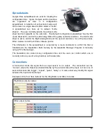
When used with a discrete output, like the D-
Pad buttons, the joystick’s position is divided
up into a series of zones, such as North,
South, East and West, which triggers a
signal when the joystick is moved into a
zone.
The discrete zones are further divided into
the Ordinal directions, North-East, South-
East, etc as well as into Inner ring and Outer
ring zones, in a manner similar to the dual
pressure thresholds for the Sip/Puff sensors.
When moving through the inner ring, a tone
is produced to indicate the joystick is within
the inner ring region and a click is produced
when either the time delay expires, or the
joystick moves into the outer ring and an
outer ring signal is triggered.
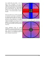
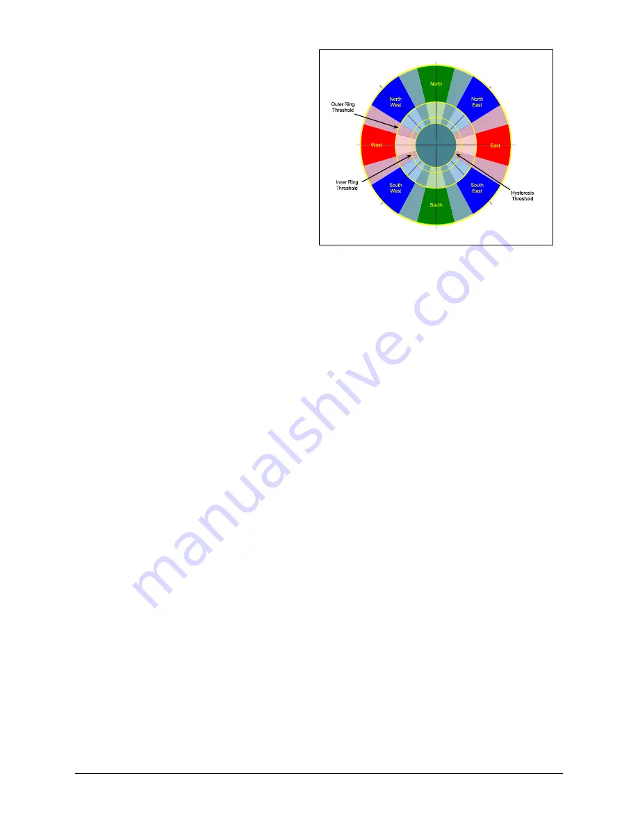
The Joystick Discrete Zones diagram shows the active areas to which the joystick can be
positioned to trigger a signal. The areas of deeper color saturation, around the Cardinal and
Ordinal directions, show where the joystick must be to be detected. The lighter mixed color
areas between the eight directions show hysteresis areas where the previous signal will remain
active until the joystick enters the next detection zone. For instance, starting at North, the
joystick can be moved from the Green area, into the Blue-Green-Gray area towards either NE or
NW and still maintain the North signal. It can move back into the Green area and no interruption
of the North signal will have occurred. However, once the joystick crosses into the Blue area
around NE or NW, that new signal becomes active and will remain active as long as the joystick
remains in the Blue area or the adjacent Blue-Green or Magenta areas.
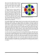
The inner and outer rings operate like the Soft and Hard Sip/Puff pressures: After entering the
Inner ring, the user must hold the joystick in the area between the Hysteresis ring and the Outer
ring until a timer expires and triggers the signal. A tone that varies with the position will sound
until the timer expires. Once the Inner ring timer has expired and the inner ring signal is
activated, the joystick has to return to the center position before moving to trigger an Outer ring
signal. Once triggered, either the inner or outer ring signals will stay active as long as the
joystick stays outside the Hysteresis ring. The joystick deflection between the Outer ring and
the maximum deflection is scaled into the pressure applied to the corresponding PS3 button, if
so mapped.
20
Illustration 4: Joystick Discrete Zones
Summary of Contents for FPS
Page 1: ...QuadStick A Gamepad for Quadriplegic Gamers User Manual...
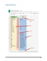
Page 26: ...Typical mode sheet 26 USB vs Bluetooth Channel Outputs Inputs Function Sheet name...
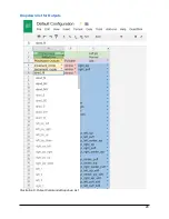
Page 28: ...Dropdown list for Outputs 28 Illustration 8 Output Commands Dropdown List...
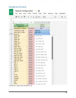
Page 29: ...Dropdown list for Inputs 29 Illustration 9 Input Sensor Dropdown List...
Page 30: ...Dropdown list for output Functions 30...
Page 50: ...The following screen captures show setting up x360ce for Rocket League in Steam 50...
Page 51: ...51...
Page 52: ...Next start the game and it should respond to the QuadStick as an XBox 360 controller 52...
Page 83: ...83 Illustration 15 Pattern for Letter I Illustration 16 Pattern for Letter K...
Page 84: ...84...

