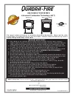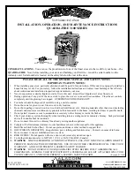
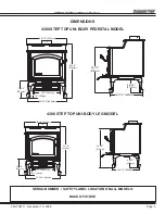
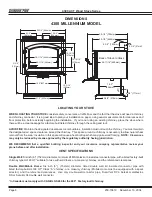


4300 ACT Wood Stove Series
Page 4
250-7061C December 10, 2004
R
LISTINGS & SAFETY CAUTIONS
These installation instructions describe the installation and
operation of the
QUADRA-FIRE 4300
woodstove. This stove
meets the U.S. Environmental Protection Agency’s 1990
particulate emission standards. The 4300 is listed by OMNI-Test
Laboratories, Inc. to UL Safety Standard 1482, and ULC S627,
and (UM) 84-HUD. The 4300 is approved for mobile home
installations when not installed in a sleeping room and when an
outside combustion air inlet is provided. The structural integrity
of the mobile home floor, ceiling, and walls must be maintained.
The stove must be properly grounded to the frame of the
mobile home and use only listed double-wall connector pipe.
Outside Air Kit, Part 831-1780, must be installed in a mobile
home installation.
Check with your local building code agency before you begin
your installation to ensure compliance with local codes, including
the need for permits and follow-up inspections. Be sure local
building codes do not supersede UL specifications and always
obtain a building permit so that insurance protection benefits
cannot be unexpectedly cancelled. If any assistance is required
during installation, please contact your local dealer.
Inspect and clean vent system frequently in accordance with the
instructions contained in this manual. Do not connect this unit
to a chimney serving another appliance.
When using optional Blower, Part 831-1701, route power cord
away from unit. Do not route cord under or in front of appliance.
Do not elevate fire. Build wood fire directly on firebrick.
Do not overfire - if heater or chimney connector glows, you are
overfiring. Stove thermometer recommended.
Operate only with the door closed. Open only to add fuel to
the fire. Operating with the door open can cause hot embers or
sparks to fall out and a fire may result.
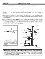
INSTALLATION MATERIALS NEEDED FOR SAFETY
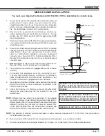
CHIMNEY CONNECTOR
(also known as flue pipe or stove
pipe): The chimney connector joins the stove to the chimney
(
see page 11
). It must be 6” (152mm) minimum diameter 24
MSG black or blued steel, or an approved air-insulated double
wall venting pipe.
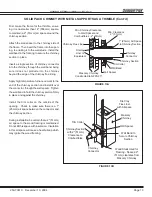
THIMBLE
: A manufactured or site-constructed device installed in
combustible walls through which the chimney connector passes
to the chimney
(see pages 12-13)
. It is intended to keep the
walls from igniting.
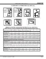
CHIMNEY SYSTEMS
:
A. APPROVED MASONRY
(see specifications on page 11)
with at least 5/8” (16mm) fire clay lining joined with refractory
cement or other listed system suitable for use with wood
stoves.
B. PREFABRICATED 6" (152mm) listed high temperature (UL
103 HT or ULC S629M) chimney. Components required by
manufacturers for installation such as the chimney support
base, firestop (as appropriate), attic insulation shield,
insulated tee, etc., are necessary to assure a safe chimney
installation. Use only components manufactured for the
chimney. Chimney installation should meet NFPA 211
standards.
FIRE SAFETY
: To provide reasonable fire safety, the following should
be given serious consideration:
1. Install at least one smoke detector on each floor of your home
to ensure your safety. They should be located away from the
heating appliance and close to the sleeping areas. Follow
the smoke detector manufacturer’s placement and installation
instructions, and be sure to maintain regularly.
2. A conveniently located Class A fire extinguisher to contend with
small fires resulting from burning embers.
3. A practiced evacuation plan, consisting of at least two escape
routes.
4. A plan to deal with a chimney fire as follows:
In the event of a chimney fire:
A. Notify fire department
B. Prepare occupants for immediate evacuation.
C. Close all openings into the stove.
D. While awaiting fire department, watch for ignition of
adjacent combustibles from overheated stove pipe, hot
embers or sparks from the chimney.
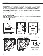
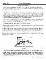
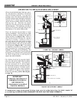
VENTING SYSTEM
The venting system consists of a chimney connector and a chimney.
These get extremely hot during use. Temperatures inside the
chimney may exceed 2000
°
F (1100
°
C) in the event of a creosote
fire. To protect against the possibility of a house fire, the chimney
connector and chimney must be properly installed and maintained. An
approved thimble must be used when a connection is made through a
combustible wall to a chimney. A chimney support package must be
used when a connection is made through the ceiling to a prefabricated
chimney. These accessories are absolutely necessary to provide safe
clearances to combustible wall and ceiling material. Follow venting
manufacturer’s clearances when installing venting system.
This stove may be connected to a lined masonry chimney or a listed
high temperature prefabricated approved metal chimney. Do not
connect it to a chimney serving another appliance. To do so will affect
the safe operation of both appliances.
WARNING! DO NOT ATTEMPT TO OPERATE THIS WOODSTOVE
WITHOUT READING AND UNDERSTANDING THESE OPERAT-
ING INSTRUCTIONS THOROUGHLY. FAILURE TO OPERATE
THIS APPLIANCE PROPERLY MAY CAUSE A HOUSE FIRE.
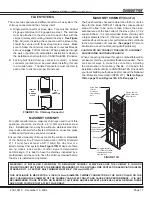
WARNING!
NEVER DRAW
OUTSIDE
COMBUSTION AIR FROM A
WALL, FLOOR OR CEILING CAVITY OR FROM ANY ENCLOSED
SPACE SUCH AS AN ATTIC OR GARAGE.
WARNING! THIS APPLIANCE IS HOT WHILE IN OPERATION
AND MAY REMAIN SO UP TO 40 MINUTES OR LONGER AFTER
THERE IS NO FUEL IN THE FIREBOX. IF THIS APPLIANCE IS
IN A HIGH TRAFFIC AREA OR CHILDREN MAY BE NEAR IT IS
RECOMMENDED THAT YOU PURCHASE A DECORATIVE BAR-
RIOR TO GO IN FRONT OF THE APPLIANCE. ALWAYS KEEP
CHILDREN AWAY WHILE IT IS OPERATING AND DO NOT LET
ANYONE OPERATE THIS APPLIANCE UNLESS THEY ARE
FAMILIAR WITH THESE OPERATION INSTRUCTIONS.