


Page 13
250-7061C December 10, 2004
4300 ACT Wood Stove Series
R
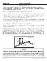
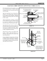
First, make the frame for the thimble, ensur-
ing it is no smaller than 14" (356mm) square,
to maintain a 2" (51mm) air space around the
chimney section.
Attach the wall spacer to the chimney side of
the frame. Then insert the frame into the open-
ing, toe nailing it to the wall studs. Install the
wall band in the framing to secure the chimney
section in place.
Insert a single section of chimney connector
into the chimney through the wall band, being
sure it does not protrude into the chimney
beyond the edge of the chimney flue lining.
Apply high temperature furnace cement to the
end of the chimney section and install it over
the connector, through the wall spacer. Tighten
the wall band to hold the chimney section firmly
in place and against the chimney.
Install the trim collar on the outside of the
opening. Check to make sure there is a 1"
(25mm) air space between the connector and
the chimney section.
During installation be certain that a 2" (51mm)
air space to the wood framing is maintained.
Do not fill this space with insulation. Insulation
in this air space will cause a heat buildup which
may ignite the wood framing.
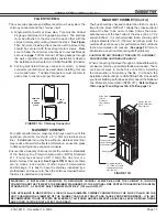
Chimney Flue Liner
Fireclay
Liner or
Equivalent
Masonry Chimney
Constructed to NFPA 211
Wall Spacer
Wall Band
Trim Collar
Chimney
Connector
1" (25mm) Air Space
to Chimney Section
Min. Clearance
2" (51mm)
Min. Chimney Clearance
to Wall Spacer and
Combustibles - 2" (51mm)
Chimney Section
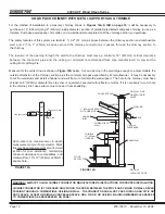
Trim Collar
Chimney Section
with 2" (51mm)
Clearance to
Combustibles
Chimney
Connector
Fire Clay
Flue Liner
with Airspace
Masonry
Chimney
Wall Band to
Secure Chimney
Section
Wood Studs Used for
Framing - Spaced 2"
(51mm) clearance from
Masonry Chimney
Wall Spacer
FIGURE 13B
FIGURE 13A
SOLID PACK CHIMNEY WITH METAL SUPPORTS AS A THIMBLE (Cont’d)


