


Page 19
250-7061C December 10, 2004
4300 ACT Wood Stove Series
R
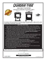
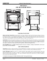
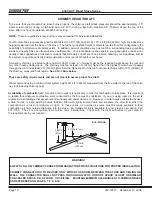
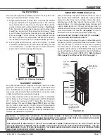
(Cut-away
view)
FRONT
COVER
SIDE
COVER (2)
4" (102mm) FLEX LINE
(Not Included)
FLEX
FLANGE
OUTSIDE AIR TERMINATION CAP
(contains rodent screen)
FIBERGLASS
SEALING
ROPE
Included in Kit:
1 front cover; fiberglass rope; 2 vent
straps; venting flange & 4 screws; termination
cap & screws. Not all materials are needed for
each model.
Items Needed for Installation
: 4” (102mm) flex pipe
in the length as required for your installation;
Phillips screwdriver; Silicone sealant; Drills and
saws necessary for cutting holes through the wall
or flooring in your home.
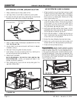
1. Remove all materials from packing box.
2. Using a #2 Phillips screwdriver, remove 2 bolts
beneath the ashcatcher. Reuse bolts to install
front cover. Be certain that the cover is pushed
back as far as possible.
3. Install side covers to each side. Slide covers into
area and secure with 4 sheet metal screws.
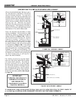
4.
Floor installation:
Cut a 4” (102mm) minimum
hole in the floor to accommodate outside air piping.
Use 4” (102mm) metal flex or rigid piping to directly
connect outside air to the unit or into
vented
crawl
space.
(Do not put flex into a non-vented crawl
space)
. Use the supplied termination cap with a
rodent screen. Seal between the floor and the
pipe with silicone to prevent moisture penetration.
Install fiberglass sealing rope under each side
of pedestal.
5.
Rear/wall installation:
(Millennium Model only,
use the knockout plate in rear of the pedestal for
exterior wall venting.) Cut a 4” (102mm) hole in
outside wall to accommodate outside air piping.
Use 4” (102mm) metal flex or rigid piping to directly
connect outside air to stove intake. Use the
supplied termination cap with a rodent screen.
Seal between the wall and the pipe with silicone
to prevent moisture penetration. Install fiberglass
sealing rope under each side of pedestal.
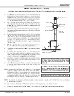
OUTSIDE AIR KIT INSTALLATION
Part 831-1780
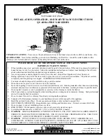
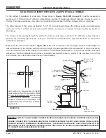
UNI-BODY
PEDESTAL MODEL
FRONT COVER
SIDE COVER
(2)
FLEX FLANGE
(if needed for rear exit.)
4" (102mm) FLEX LINE
(Not Included)
OUTSIDE AIR
TERMINTATION CAP
(contains rodent screen)
FIBERGLASS SEALING ROPE
4-3/8" (111mm)
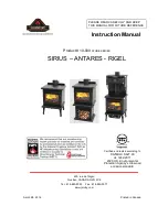
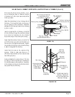
CL
FRONT
COVER
SIDE
COVER (2
)
4" (102mm) FLEX LINE
(Not Included)
OUTSIDE AIR TERMINATION
CAP
(contains rodent screen)
FLEX
FLANGE
MILLENNIUM MODEL