


Page 17
250-7061C December 10, 2004
4300 ACT Wood Stove Series
R
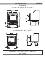
PEDESTAL MODEL
1 Place protective pad or stove pallet on floor.
2. Lay body of stove on its back on protective pad or
pallet.
3. Loosen screws on adapter and slide pedestal over
adapter on bottom of stove
4. Line up holes in sides of pedestal with holes in
adapter.
5. Securely tighten pedestal into place.
6. Carefully stand stove up and place in desired loca-
tion.
7. Slip wooden decorative strips onto pedestal edges.
8. Open door of stove and check to make sure firebricks
and ceramic blanket are in their proper locations
(see
pages 24-25)
.
PEDESTAL OR LEG KIT INSTALLATION
LEG MODEL
1. Remove leg mounting brackets packaged inside fire-
box.
2. Place protective pad or stove pallet on floor.
3. Lay body of stove on its back on protective pad or
pallet.
4 Remove the bolts, using a 9/16” Hex Head socket or
wrench, from the adapter and save.
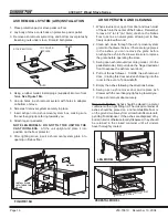
5. Secure mounting brackets to the bottom of the stove
with 1/4”-20 Phillips screws. These screws are located
on the outer skin at the bottom rear of the stove.
See
Figure 17A.
6. Loosely assembly bolts into the corner of the mounting
brackets.
7. Slide legs onto mounting brackets and tighten.
8. Carefully stand stove up and place in desired location.
9. Use leveling bolts on legs to stabilize and level stove.
10. Open door of stove and check to make sure firebricks
and ceramic blanket are in their proper locations
(see
pages 24-25).
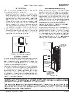
If installing legs, remove
these screws to attach
leg brackets to bottom
of stove
LEG MOUNTING BRACKETS
(packaged inside stove firebox).
CAUTION! DO NOT TILT THE UNIT ON THE
CAST IRON LEGS. Lift the unit upright and
place it into position on the floor protector.
Figure 17A
Figure 17B
WARNING: DO NOT OPERATE STOVE BEFORE FULLY ASSEMBLING ALL
COMPONENTS. BURNING YOUR STOVE WITHOUT A PEDESTAL OR LEG
KIT ATTACHED WILL VOID YOUR WARRANTY AND COULD PRESENT A
SAFETY HAZARD.