


Page 11
250-7061C December 10, 2004
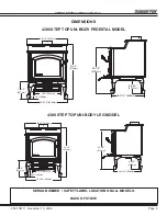
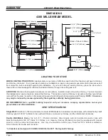
4300 ACT Wood Stove Series
R
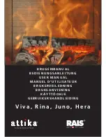
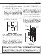
There are two separate and different parts to a flue system: the
chimney connector and the chimney itself.
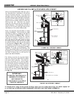
A. Single wall connector or stove pipe. This must be at least
24 gauge mild steel or 26 gauge blue steel. The sections
must be attached to the stove and to each other with the
crimped (male) end pointing toward the stove.
See Figure
11A.
All joints, including the connection at the stove collar,
should be secured with three sheet metal screws. Make
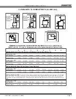
sure to follow the minimum clearances to combustibles as
set out on
page 7
of this manual. Where passage through
the wall, or partition of combustible construction is desired,
the installation shall conform to CAN/CSA-B365 (Canada).
B. Factory-built listed chimney connector (vented). A listed
connector (vented) must be used when installing this unit
in a mobile home. The listed connectors must conform to
each other to ensure a proper fit and seal.
FLUE
GAS
DIRECTION
CRIMPED
END
TOWARDS
STOVE
FLUE SYSTEMS
WARNING!! IF INSTALLING THIS MODEL TO A MASONRY CHIMNEY, ALWAYS BE SURE THE CHIMNEY IS IN GOOD
CONDITION AND THAT IT MEETS THE MINIMUM STANDARDS OF THE NATIONAL FIRE PROTECTION ASSOCIATION (NFPA)
STANDARD 211. A FACTORY BUILT CHIMNEY MUST BE 6” (152mm) UL103 HT.
THIS APPLIANCE IS MADE WITH A 6 INCH (152mm) DIAMETER CHIMNEY CONNECTOR AS THE FLUE COLLAR ON THE
UNIT. CHANGING THE DIAMETER OF THE CHIMNEY CAN AFFECT DRAFT AND CAUSE POOR PERFORMANCE. IT IS NOT
RECOMMENDED TO USE OFFSETS OR ELBOWS AT ALTITUDES ABOVE 4000 FEET ABOVE SEA LEVEL OR WHEN THERE
ARE OTHER FACTORS THAT AFFECT FLUE DRAFT.
FIGURE 11A - Chimney Connector
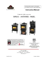
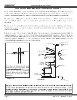
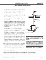
Thimble Assembly:
12" (305mm) of brick
separation between
clay liner and
combustibles.
Fireclay liner 5/8"
(16mm) Minimum
or Equivalent.
Sill support
Header
Wood Stud 2"
(51mm)
Clearance
from chimney
wall
Fireclay liner 5/8"
(16mm) Minimum
or Equivalent.
The flue should be checked to determine that it is not too
large for the stove. NFPA 211 allows the cross-sectional
area of the flue to be no more than 3 times the cross-
sectional area of the flue collar of the stove (28 x 3 = 84
square inches). It is recommended that a chimney with
a larger diameter than 6” (152mm) be relined, since the
oversized flue can cause poor performance and contribute
to the accumulation of creosote. (
See page 10
for more
information about troubleshooting draft problems).
CAUTION! DO NOT CONNECT THIS UNIT TO A CHIMNEY
FLUE SERVING ANOTHER APPLIANCE.
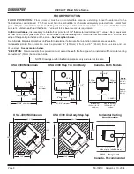
When connecting the stove through a combustible wall to
a masonry chimney, special methods are needed. There
are several ways to make this connection, including
the construction of a masonry thimble. In Canada, the
installation shall conform to CAN/CSA-B365. Check with
your local building authorities and/or consult the National
Fire Protection Association (NFPA 211).
Refer to Figure
13B on page 13 and Figures 14A & 14B on page 14
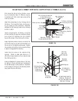
MASONRY CHIMNEY
FIGURE 11B
Ensure that a masonry chimney meets the minimum standards
of the National Fire Protection Association (NFPA) Standard
211. It must have at least a 5/8" (16mm) fire clay liner or a
listed chimney liner system.
See Figure 11B
. Make sure there
are no cracks, loose mortar or other signs of deterioration
and blockage. It is best to have the chimney inspected by a
professional, and be sure to have the chimney cleaned before
the stove is installed and operated.
MASONRY CHIMNEY (Cont’d)
For optimal performance, masonry chimneys used to vent this
appliance should be lined with a 6" (152mm) stainless steel
liner. Installations into a clay flue without a stainless steel liner
may reduce draw which affects performance, cause the glass
to darken and produce excessive creosote.