


4300 ACT Wood Stove Series
Page 14
250-7061C December 10, 2004
R
*
*
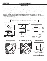
Floor
Protector
Chimney
Connector
Combustible
Ceiling
Combustible Wall
Insulated " T "
Flashing
Listed Cap
Maintain 2" (51mm)
Clearance Through Eave
*
Listed
Chimney Pipe
Chimney
Connector
To Stove
Trim Collar
on Inside
Wall
Combustible Outside Wall
2" (51mm)
Clearance
Listed Chimney
Insulated " T "
Wall Support
Wall Spacer on
Outside Wall
*
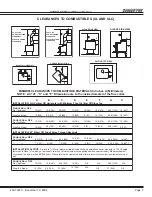
Refer to Clearances to Combustibles
CONNECTION TO A METAL PRE-FABRICATED CHIMNEY
When a metal prefabricated chimney is used,
the manufacturer’s installation instructions
must be followed precisely. You must also
purchase (from the same manufacturer) and
install the ceiling support package or wall pass-
through and “T” section package, firestops
(where needed), insulation shield, roof flashing,
chimney cap, etc. Maintain the proper
clearance to the structure as recommended by
the manufacturer. This clearance is usually a
minimum of 2” (51mm), although it may vary by
manufacturer or for certain components.
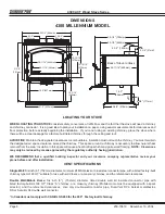
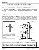
There are basically two methods of metal
chimney installation. One method is to install
the chimney inside the residence through the
ceiling and the roof
(Figure 14A
). I
nstall an
attic insulation shield to maintain the specified
clearance to insulation. Insulation in this air
space will cause a heat buildup which may ignite
the ceiling joists.
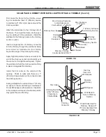
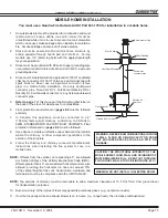
The other method is to install
an exterior chimney that runs up the outside
of the residence
(Figure 14B)
. This method
of installation requires at a minimum a wall
pass-through device, a wall support package,
insulated “T” section and roof flashing. The
components illustrated may not look exactly like
the system you purchase, but they demonstrate
the basic components you will need for a
proper and safe installation.
Combustible Wall
Floor
Protector
Chimney
Connector
Ceiling Support
Listed Chimney
Maintain 2" (51mm)
Clearance
Listed Cap
Storm Collar
Flashing
*
*
*
Refer to Clearances
to Combustibles
Combustible
Ceiling
Joists
Chimney
Connector
To Stove
Ceiling
Support
Specified
Clearance
Attic
Insulation
Shield
Listed
Chimney
FIGURE 14A - INTERIOR CHIMNEY
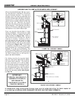
The chimney must be the required height
above the roof or other obstruction for safety
and proper draft operation. The chimney
must be a minimum of 3 ft. (91cm) higher
than the highest point where it passes through
the roof, and at least 2 ft. (61cm) higher
than the highest part of the roof or structure
that is within 10’ ft. (305cm) of the chimney,
measured horizontally
(2-10-3 Rule Figure
on page 10).
FIGURE 14B -EXTERIOR CHIMNEY
In Canada when using a factory-built chimney, make sure it is safety listed, Type UL 103 HT CLASS "A"
or conforming to CAN/ULC-S629, STANDARD FOR 650°C FACTORY-BUILT CHIMNEYS.
IMPORTANT!
Follow the manufacturer’s
installation instructions
and maintain the
manufacturer’s specified
clearance distances.