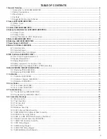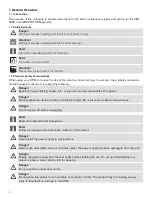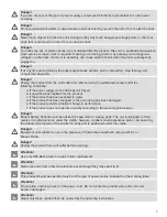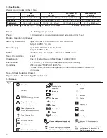
14
9.3 Display replacement
The Display is held in place by the top end cap and the bottom display holder.
To replace Display, first remove cover following steps 1 through 6 above.
10. Remove 20 pin Ribbon Cable from ZIF connector to remove display (REF DES J3).
11. Connect Ribbon Cable, insert Display into bottom display holder.
9.4 battery replacement for real time clock
Follow steps 1 through 6 to remove speaker as described above.
Once LCD Display is out of the way, simply slide the 3V Battery out of its retainer, and insert the new one.
Reassemble in reverse order.
9.5 PCb Printed Circuit board (PCb) or PCba (assembly)
Dissasemble PRO Controller following steps 1 through 11 above
Remove battery
Remove bottom Display holder by removing the 2 screws.
Reattach all components to new board.
Reassemble front, back and end caps.
note:
When replacing cover, be careful not to damage Keypad ribbon cable.
10 MAIN PRINTED CIRCUIT BOARD (PCB)
10.1 Replacing PCb (480/480E)
attention:
The Printed Circuit Board is a Static Sensitive Device. Repair should be attempted by qualified
personnel only. All anti-static handling procedures should be observed.
Removal:
1. Remove bottom cover of device (refer to section 2.1).
2. Remove all connectors from the main PC board.
3. The PC board may be removed by one of three procedures depending on when a particular device
was manufactured:
a. Gently push the PC board toward the top cover until the nylon standoff is disengaged from the board.
b. Or, remove the nylon screws securing the PC board to the nylon standoffs.
c. Or, remove the nylon nuts securing the Shield, insulator and PC board to the nylon standoffs. Lift the
shield off.
Lift the insulator off. Remove the four Spacers. Lift the PC board from the standoffs.
Installation:
1. Place the main PC board above the nylon standoffs.
2. While guiding the nylon standoffs into the mounting holes, place the PC board on them.
3. To reinstall the PC board perform the following procedure (depending on when the device was
manufactured):
a. Gently push the PC board toward the bare frame until the PC board seats firmly against the stopping
pad on the nylon standoff.
b. Or, install the nylon screws securing the PC board to the nylon standoff.
c. Or, place the PC board on to the four standoffs. Install the four Spacers on the standoffs. Place the
insulator into the Shield. Place the Shield on to the standoffs and route the cables through the slots in
the Shield. Position the ferrite loops as close to the Shield as possible and secure such that they do
not contact any moving parts.
4. Install the connectors into main PC board.
Summary of Contents for 480
Page 1: ...480 480E 480E PRO CPM Service and Technical Manual 2011 QAL Medical 05070812 3 Rev C 08 11...
Page 2: ......
Page 25: ...25 14 Assembly Drawings 14 1 Main Assembly...
Page 26: ...26 14 2 Thigh Assembly...
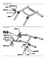
Page 27: ...27 14 3 Cradle Sub Assembly 480 L480SA011 480E L480SA022...
Page 28: ...28 14 4 Foot Cradle Assembly...
Page 29: ...29 14 5 Ballscrew Assembly...
Page 30: ...30 14 6 480 U Bracket Slider Assembly...
Page 31: ...31 14 7 480E 480E PRO U Bracket Slider Assembly...
Page 32: ...32 14 8 480E or 480E PRO Motor Assembly Faulhaber...
Page 33: ...33 14 9 480E PRO ONLY Motor Assembly Maxon...
Page 34: ...34 14 10 Motion Controller Assembly 480 480E...
Page 36: ...36 14 12 480 Wiring Diagram...
Page 37: ...37 14 13 480E Wiring Diagram...
Page 39: ...39 14 15 480 480E Electrical Schematic...
Page 40: ...40...
Page 41: ...41...


