13
6. Gently push the cable into the appropriate cutout in the housing.
7. Position the back controller housing making sure that the cable is not pinched between the two halves.
8. Install the four Phillips screws in the holes on the back of the controller and tighten.
9. Replace back cover label on back side of controller housing.
8.3 Controller Printed Circuit board
Removal:
1. Remove back cover label from controller.
2. Using a No. 2 Phillips head screwdriver, remove the four screws from the back of the controller.
3. Remove the back controller housing.
4. Carefully pull the controller board straight away from the front half of the controller housing.
5. Cut the ty-rap which holds the cable flat to the board.
6. Carefully slide cable connector from the board-mounted connector pins.
7. Lift the board out of the controller housing.
Installation:
1. Slide the cable connector onto the board-mounted connector pins.
2. Carefully insert the board into the front controller housing.
3. Gently push the cable into place in the cutout of the housing and tie-wrap the cable flat to the board.
4. Reinstall the back of the controller housing, making sure that the cable is not pinched between the
two halves.
5. Reinstall the four Phillips head screws in the holes on the back of the controller and tighten.
6. Place back cover label on back side of controller housing.
9 PRO CONTROLLER PENDANT (480E PRO Only)
attention:
The PRO Controller Pendant is a Static Sensitive Device. Repair should be attempted by qualified
personnel only. All anti-static handling procedures should be observed.
note:
It will be necessary to access the settings mode to access the systems setting service and error log. To
enter the "settings mode" enter the following key sequence: Up Direction Arrow, Right Arrow, Down Arrow, Left
Arrow, Select.
9.1 front Cover/Key pad replacement
note:
The Front Cover and Keypad (NG-SA001) are a single unit.
1. Remove all 4 screws from back of unit.
2. Pull off back and fish paper insulator.
3. Carefully remove front (which contains keypad); it is connected to the Printed Circuit Board (PCB) with a
ZIF connector (REF DES J8).
4. Release Key Pad ribbon cable by retracting the 2 tabs on either side of the ZIF connector.
note:
The ribbon cable should release with minimal force.
9.2 Speaker replacement
Remove Cover following steps 1 through 4 above.
5. Remove Top End Cap.
6. Carefully move LCD display out of the way.
7. Remove 2-lead connector on right hand side of board.
8. Remove Bottom End Cap and replace with new sub-assembly.
Reverse above order to put the PRO Controller back together.
Summary of Contents for 480
Page 1: ...480 480E 480E PRO CPM Service and Technical Manual 2011 QAL Medical 05070812 3 Rev C 08 11...
Page 2: ......
Page 25: ...25 14 Assembly Drawings 14 1 Main Assembly...
Page 26: ...26 14 2 Thigh Assembly...
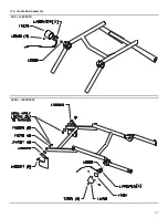
Page 27: ...27 14 3 Cradle Sub Assembly 480 L480SA011 480E L480SA022...
Page 28: ...28 14 4 Foot Cradle Assembly...
Page 29: ...29 14 5 Ballscrew Assembly...
Page 30: ...30 14 6 480 U Bracket Slider Assembly...
Page 31: ...31 14 7 480E 480E PRO U Bracket Slider Assembly...
Page 32: ...32 14 8 480E or 480E PRO Motor Assembly Faulhaber...
Page 33: ...33 14 9 480E PRO ONLY Motor Assembly Maxon...
Page 34: ...34 14 10 Motion Controller Assembly 480 480E...
Page 36: ...36 14 12 480 Wiring Diagram...
Page 37: ...37 14 13 480E Wiring Diagram...
Page 39: ...39 14 15 480 480E Electrical Schematic...
Page 40: ...40...
Page 41: ...41...


