12
(Steps for both 480 and 480E):
5. Remove back cover label from controller.
6. Using a No. 2 Phillips screwdriver, remove the four screws from the back of the controller to open the
controller housing.
7. Carefully pull the controller board straight away from the face of the controller housing.
8. Cut the ty-rap which holds the cable flat to the board.
9. Carefully slide cable connector from the board-mounted connector pins.
Installation:
1. Carefully slide cable connector onto the main controller board connector.
2. Position the cable so the shielded cable comes up over the edge of the controller board. Ty-rap the cable
in place flat to the board.
3. Guide the pins from the controller keypad board into the connector on the main controller board. Carefully
squeeze the two boards together until the connector is well seated.
4. Reinstall the back of the controller housing.
5. Reinstall the four Phillips screws and tighten.
6. Replace the back cover label.
(Steps 7-11 for 480 only)
7. Slide the board end of the cable through the opening in the base of the unit.
8. Re-position the strain relief.
9. Connect the cable to the board-mounted connector.
10. Join the controller and ribbon cables with ty-raps
11. Reinstall the bottom cover (refer to section 2.1).
8.2 Controller Keypad
Removal:
1. Remove back cover label from controller.
2. Using a No. 2 Phillips screwdriver, remove the four screws from the back of the controller.
3. Remove the back of the controller housing.
4. Carefully pull the control board straight away from the face of the controller housing.
5. Lift the board out of the controller housing.
6. Lift the LCD window out of the front half of the controller.
7. Using a 1/4” nut driver remove the four locknuts from the inside of the front half.
8. Carefully lift the controller housing away from the front bezel.
9. Lift out the controller control board to remove the keypad.
Installation:
1. Gently press keypad into position inside the bezel, checking to be sure that the locator pins have come
through the pad.
2. Position the controller control board so that the locator pins also pass through the appropriate holes in the
PC board.
3. Place the front controller housing on top of the bezel and control board assembly, and secure with four
locknuts.
4. Place the LCD window into the opening, being sure that the printing is readable from the front of the
controller.
5. Carefully position the main controller board in the front half of the controller housing.
Summary of Contents for 480
Page 1: ...480 480E 480E PRO CPM Service and Technical Manual 2011 QAL Medical 05070812 3 Rev C 08 11...
Page 2: ......
Page 25: ...25 14 Assembly Drawings 14 1 Main Assembly...
Page 26: ...26 14 2 Thigh Assembly...
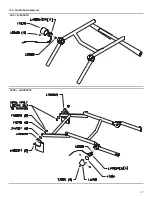
Page 27: ...27 14 3 Cradle Sub Assembly 480 L480SA011 480E L480SA022...
Page 28: ...28 14 4 Foot Cradle Assembly...
Page 29: ...29 14 5 Ballscrew Assembly...
Page 30: ...30 14 6 480 U Bracket Slider Assembly...
Page 31: ...31 14 7 480E 480E PRO U Bracket Slider Assembly...
Page 32: ...32 14 8 480E or 480E PRO Motor Assembly Faulhaber...
Page 33: ...33 14 9 480E PRO ONLY Motor Assembly Maxon...
Page 34: ...34 14 10 Motion Controller Assembly 480 480E...
Page 36: ...36 14 12 480 Wiring Diagram...
Page 37: ...37 14 13 480E Wiring Diagram...
Page 39: ...39 14 15 480 480E Electrical Schematic...
Page 40: ...40...
Page 41: ...41...


