SECTION 3
Pronar RC2100-2
3.5
3.2.2 TRAILER'S DRAWBAR
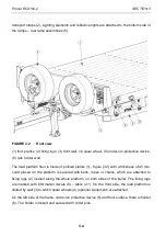
In the front part of the trailer - figure (3.3), there is a drawbar (1) with shock absorbing springs
(2). Drawbar hitching eye (3) is bolted to the drawbar faceplate. Depending on configuration,
fixed drawbar with a
∅
50mm eye, fixed drawbar with a
∅
40 mm eye, rotating drawbar with a
∅
50 mm eye or K80 ball drawbar can be used. On the left side of the drawbar, there is a
parking stand (4) (mechanical or hydraulic). On the upper profile of the drawbar there is a
holder for installing bracket for conduit connectors (5).
FIGURE 3.3
RC2100-2 trailer drawbar
(1) drawbar, (2) spring, (3) rotating drawbar with a
∅
50 eye, (4) parking stand, (5) bracket for
conduit connectors
3.2.3 SUSPENSION
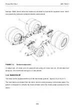
Axles (1) – figure (3.4) in a tandem arrangement, are attached to parabolic leaf springs (3)
using an absorber plate and U bolts. The parabolic leaf springs are connected together by
means of rocker arms (2). The complete axle system is connected with the frame by means
of fixing brackets welded to the chassis longitudinal members and axle system pins. Axles
are made from square bars terminated with pins, on which wheel hubs are mounted on cone
Summary of Contents for RC2100-2
Page 2: ......
Page 6: ......
Page 10: ...5 11 TROUBLESHOOTING 5 31 ...
Page 11: ...SECTION 1 BASIC INFORMATION ...
Page 24: ...PRONAR RC2100 2 SECTION 1 1 14 ...
Page 25: ...SECTION 2 SAFETY ADVICE ...
Page 40: ...Pronar RC2100 2 SECTION 2 2 16 FIGURE 2 3 Locations of information and warning decals ...
Page 41: ...SECTION 3 DESIGN AND OPERATION ...
Page 59: ...SECTION 4 CORRECT USE ...
Page 78: ...Pronar RC2100 2 SECTION 4 4 20 ...
Page 79: ...SECTION 5 MAINTENANCE ...
Page 110: ...Pronar RC2100 2 SECTION 5 5 32 FIGURE 5 12 Lubrication points part 1 ...
Page 111: ...SECTION 5 Pronar RC2100 2 5 33 FIGURE 5 13 Lubrication points part 2 ...
Page 119: ...NOTES ...
Page 120: ... ...
Page 121: ...ANNEX A Tyre dimensions LP TYRES WHEEL RIM 1 215 75 R17 5 135 133 J 17 5x6 75 ...


