PRISMJET 54 Gen2 Operation Manual Download Page 276

Maintenance

PrismJET 54 Gen2 OPERATION MANUAL

286

6.5  Long Storage and Initial Ink Charging

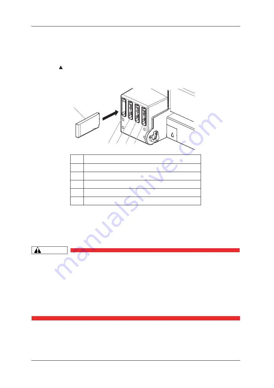
3. Insert the ink cartridges into Ink cartridge slots.

Make sure that the ink cartridges are inserted into the correct slots.
Match the mark in front of the slot and the color of the ink before inserting the ink cartridge.

Keep   mark of the ink cartridge facing up and insert towards the printer side.

Insert the ink cartridge all the way to the end of the slot.

“Ink Refill **%” is displayed on the operation panel and initial ink charge starts.

Initial ink charge takes about four minutes.
Ink charging operation and pause operation are repeated during the initial ink charge.

When “100%” is displayed, the initial ink charge is complete.

CAUTION

• Do not perform the following operations during ink charging. If charging is 

interrupted, ink will be lost when charging is resumed.

• Do not turn OFF the printer.

• Do not unplug the power cable.

• Do not open the front cover.

• Do not open the maintenance cover.

• Do not raise the media loading lever.

After the initial ink charge is complete, “Media End” is displayed on the operation panel.

No.

Name

1

Ink cartridge

2

Ink cartridge slot K

3

Ink cartridge slot C

4

Ink cartridge slot M

5

Ink cartridge slot Y

2

3

4

5

1

Summary of Contents for 54 Gen2

Page 1: ......

Page 2: ......

Page 3: ...uctions This chapter explains warning terms safety precautions and warning labels on the product that operators and people who install this product need to know WARNING When installing and operating t...

Page 4: ...d into three stages Understand the meanings of the following warning terms and follow the contents instructions in this manual Warning Meaning Used for dangerous situations where death or serious inju...

Page 5: ...ct an earth wire to the following places Gas pipes There is a possibility of ignition and explosion Earth wire of telephone cables and lightning rods Heavy current might flow whenever lightning strike...

Page 6: ...ling of the power cable could cause a fire Make sure that no foreign substances such as dust etc are stuck to the power plug Make sure that the power plug is firmly inserted to the edge of the power s...

Page 7: ...Do not touch the tip of the cleaning stick The print head may be damaged because of oil from your hands Never put water etc on the tip of the cleaning stick Doing so may damage the print head Do not...

Page 8: ...p the scroller may be damaged Pay attention to the following points when cutting roll media Mishandling the razor blade may cause a cut on your finger or hand When you hold media do not place your fin...

Page 9: ...ling the warning labels be careful about the following points NOTE Check whether all the warning labels can be read If the letters or illustrations on the label are not clear remove the dirt from the...

Page 10: ...ing labels 1 2 Hot Surface Caution Label The surface may get hot and may cause burn injury Do not touch with your hand for at least 30 minutes after turning off the printer 3 Pinch hazard Keep hands a...

Page 11: ...rating instruction labels with simplified operation procedures where special attention is required during operation Make sure to fully understand the locations and contents of the labels before operat...

Page 12: ...ary to replace the operating instruction labels if they are damaged lost or unreadable If the operating instruction labels have to be replaced contact SIGNWarehouse Product Support or your local Prism...

Page 13: ...PrismJET 54 Gen2 OPERATION MANUAL Product overview 23 2 Product overview This chapter explains the names and functions of each part...

Page 14: ...ng or releasing media 2 Operation panel Operation condition setting printer display and various function settings are performed 3 Front cover Used for preventing a user from coming in contact with the...

Page 15: ...9 Maintenance cover L Used to prevent the user from touching the inner mechanical section Open and close in the following cases When cleaning around the print head When cleaning the color sensor When...

Page 16: ...Set the scroller here when using the roll media 4 Media feed slot Used for feeding media 5 Ink cartridge slot Insert the ink cartridge 6 Media guide Used for feeding media smoothly when the media is...

Page 17: ...Names of each operation key and status display along with the functions are explained TIP Refer to the following for details regarding the operation method of the operation panel When performing menu...

Page 18: ...e set and shifts to the next hierarchy The setting is determined and saved Cutting key Cuts the media when pressed for more than two seconds 3 Pause key Pauses printing Cancel key When printing When p...

Page 19: ...e LCD Lamp blinks The remaining amount of ink is low Lamp OFF There is no error 11 High lamp Green Lamp ON The head height is set to High When the Low lamp is also on The head height is set to Middle...

Page 20: ...alarm 7 2 3 Error requiring restart If the error persists even when the malfunction is fixed contact your local MUTOH dealer 16 Normal lamp Green Lamp ON Cleaning Mode is set to Normal When the Long l...

Page 21: ...displayed on LCD monitor 5 7 Display menu 5 7 4 Remain Ink menu In the normal operation 2 2 1 Normal During printing To display ink or cartridge errors 7 2 2 Message type error display and remedies T...

Page 22: ...ng ink amount More than 80 less than 100 2 Remaining ink amount More than 60 less than 80 3 Remaining ink amount More than 40 less than 60 4 Remaining ink amount More than 20 less than 40 5 Remaining...

Page 23: ...rom the operation panel The various functions for printing can be performed on the operation panel Display contents in the LCD monitor of the operation panel are as follows 2 2 3 Changing printer stat...

Page 24: ...m either of the following operations to shift the operation panel to the Normal display Press the Cancel or Menu key on the operation panel In the Setup menu leave the keys untouched for three minutes...

Page 25: ...PrismJET 54 Gen 2 OPERATION MANUAL Before using 35 3 Before using This chapter explains necessary steps before using the printer...

Page 26: ...nter is used Use a power cord set which is equipped with a protective earth and securely connect it to the outlet Do not use a damaged power cable It could lead to an electric shock and fire CAUTION P...

Page 27: ...w to install the power cable 1 Make sure that the printer is turned OFF NOTE The power is ON when the Power key of the operation panel is pressed in Press the key once again to turn OFF the power 2 Co...

Page 28: ...or fire may occur Do not connect an earth wire to the following places Gas pipes There is a possibility of ignition and explosion Earth wire of telephone cables and lightning rods Heavy current might...

Page 29: ...arth connection cannot be established or if the earth connection is not given When the power supply of the printer is ON do not pull out the power cable from the power socket Whenever the plug is pull...

Page 30: ...r ON 1 Press the Power key on the operation panel to turn ON the printer Power lamp on the operation panel turns on blue The printer starts initial operation When the initial operation is complete the...

Page 31: ...ion panel is in the following status the power is ON The Power key is pressed in Power lamp is on blue Press the key once again to turn OFF the power The printer starts the procedure to turn the power...

Page 32: ...Before using PrismJET 54 Gen2 OPERATION MANUAL 42 3 2 Turning the power ON OFF 3 Raise the media loading lever when the product is not used for a long time No Name 1 Media loading lever 1...

Page 33: ...nk Be cautious that ink does not get into your eye or make a contact with your skin When ink gets into your eye or make a contact with your skin wash with water immediately If left as it is it may cau...

Page 34: ...gs strong shakes Doing so may cause ink leakage Do not disassemble ink cartridges or ink bags A disassembled ink cartridge cannot be used Make sure to use the dedicated cleaning fluid Model number PRN...

Page 35: ...stall the 220 ml ink cartridge 1 Turn the printer ON The printer starts the initializing operation After the initial operation is compete Start Ink Charge E is displayed on the operation panel 2 Press...

Page 36: ...installed Busy Washing is displayed on the operation panel and the printer starts charging the cleaning fluid When the cleaning fluid has been charged Remove Cartridges is displayed on the operation p...

Page 37: ...and press the Enter key to perform head cleaning 6 Press the Enter key on the operation panel Insert InkCartridges is displayed on the operation panel 7 Take out the new ink cartridge from the bag 8 A...

Page 38: ...ge starts Initial ink charge takes about four minutes Ink charging operation and pause operation are repeated during the initial ink charge When 100 is displayed the initial ink charge is complete CAU...

Page 39: ...inted lines become blurred The data is partially not printed In such cases follow 6 2 3 Head cleaning and perform Little Charge Then check the printing result If there is no improvement in the print r...

Page 40: ...on this printer Follow the procedure below to install the high capacity pack adapters 1 Turn the printer ON The printer starts the initializing operation After the initial operation is compete Start I...

Page 41: ...installed Busy Washing is displayed on the operation panel and the printer starts charging the cleaning fluid When the cleaning fluid has been charged Remove Cartridges is displayed on the operation p...

Page 42: ...InkCartridges is displayed on the operation panel 7 Take out the new ink bag from the bag 8 Install the ink bag and smart chip card to high capacity pack adapter 9 Agitate the ink bag To prevent the i...

Page 43: ...aning fluid bag will not be usable Insert the high capacity pack adapter all the way to the end of the slot When a high capacity pack adapter is installed Ink Refill is displayed on the operation pane...

Page 44: ...ially not printed In such cases follow 6 2 3 Head cleaning and perform Little Charge Then check the printing result If there is no improvement in the print result even after performing Little Charge l...

Page 45: ...ller included with the printer NOTE The following roll media can be loaded on the scroller included with the printer Media tube with a diameter of three inches Less than 6 inches 150 mm in outer diame...

Page 46: ...scroller make sure that the paper is rolled counter clockwise when seen from the fixed media stopper 3 Insert the roll media all the way till its core touches the right edge of the fixed media stopper...

Page 47: ...ATION MANUAL Before using 3 4 Loading media 57 5 Set the scroller on the holder with the fixed media stopper on the ink cartridge slot side No Name 1 Scroller 2 Fixed media stopper 3 Ink cartridge slo...

Page 48: ...the printer ON CAUTION Do not operate the media loading lever during the initial operation or printing The print head portion may touch the pressurizing roller portion and cause a malfunction The pri...

Page 49: ...Set the roll media to the media feed slot NOTE If the end of the roll media is not wound tightly wind it tightly again and then load it 4 Open the front cover to pull out the roll media No Name 1 Rol...

Page 50: ...the roll media with the scroller to remove a media bend or slant 6 Lower the media loading lever NOTE When loading the new roll media cut the front edge of the media if it is not straight 4 4 4 Cutti...

Page 51: ...fore using 3 4 Loading media 61 7 Close the front cover The User type setup menu is displayed on the operation panel TIP To change the media type follow 3 4 4 Setting the User Type Setting and set the...

Page 52: ...the procedure below to release Pressure arms 1 Raise the media loading lever 2 Push the release switches of Pressure arms further in that are holding the sides of the media When the release switch is...

Page 53: ...Gen2 OPERATION MANUAL Before using 3 4 Loading media 63 3 If media still gets creases increase the number of Pressure arms to release NOTE The media may still get creases even when more Pressure arms...

Page 54: ...ns how to set the user type setting Follow the procedure below to set the user type setting 1 Turn ON the printer and load media After loading the media the printer enters the user type setting menu T...

Page 55: ...tarts media initial operation without specifying a user defined setting Pressing the Cancel key on the operation panel No keys on the operation panel are pressed for 30 seconds After media initial ope...

Page 56: ...rrectly 1 Turn ON the printer and load the media 3 4 2 Setting Roll Media 2 Confirm that the printer functions normally 3 Display the Test Print menu on the operation panel a Press the Menu key on the...

Page 57: ...el The display shifts to the Test Print menu 5 2 Test Print Menu 4 Press the key or key on the operation panel to select an item for printing from the following items Nozzle Check Nozzle Check F Mode...

Page 58: ...elected item TIP Refer to the following for details on each of the print list items 3 5 1 Nozzle check to 3 5 5 Palette print 6 Repeat step 4 to step 5 when performing test print for other items 7 Pre...

Page 59: ...u 5 1 26 Select Nozzle menu NOTE If the nozzle check result indicates that the checked points are blurred or missing clean the head 6 2 3 Head cleaning Perform the nozzle check once again at the end o...

Page 60: ...s on the print head NOTE If the nozzle check result indicates that the checked points are blurred or missing clean the head 6 2 3 Head cleaning Perform the nozzle check once again at the end of the wo...

Page 61: ...e following printing conditions Print Mode Effect Preset Pre heater temperature Preset platen heater temperature Preset dryer temperature Adjustment value TIP Refer to the following for printing proce...

Page 62: ...FrontInterlace Auto 26 Select Nozzle 1 Print 2 Nozzle Settings Nozzle ALL Ink Status SmartChip KCMY 85 85 28 24 Life Times Head E F Pump E F CR Motor E F PF Motor E F SleepModeSettings CleaningTimer...

Page 63: ...5 Palette print Palette print is executed for the color demonstration NOTE When the selected print mode of the user type is Quality or Production Palette menu is not displayed 5 1 1 1 1 Print Mode me...

Page 64: ...isaligned beforehand Adjust Print requires at least 21 6 550 mm printable width Before printing make sure that there is sufficient width on the media If printable width is less than 21 6 550 mm your p...

Page 65: ...Standard Adjust Print 3 6 4 Custom Adjustment Pattern 3 6 2 Auto Adjust Print Perform the automatic adjustment using the embedded color sensor This menu is made up with the following menus Follow the...

Page 66: ...n panel a Press the Menu key on the operation panel Menu1 Setup is displayed on the operation panel b Press the key on the Operation panel Set1 User Type is displayed on the operation panel c Press th...

Page 67: ...using 3 6 Adjust Print 77 d Press the key or key on Operation panel to select the user type setting e Press the Enter key on the operation panel 1 Print Mode is displayed on the operation panel f Pres...

Page 68: ...170 m If the default value has been changed the changed value is displayed h Press the key or key and enter the thickness of the paper to use in the range of 80 m to 1 300 m This setting is the same a...

Page 69: ...on the operation panel The display enters the Adjust Print menu 5 1 1 1 3 Adjust Print menu k Press the key or key and enter the adjustment pattern from ALL Standard or any specific pattern between Ad...

Page 70: ...d the message Auto Adjust Succeeded will appear on the panel If failed the message Auto Adjust Failed will appear on the panel 5 Press the Enter key on the Operation panel The previous setup menu is d...

Page 71: ...Perform rough adjustment first when the degree of misalignment is difficult to determine 3 Print the confirmation pattern and check if the printer is adjusted properly 3 6 3 1 Standard Confirmation Pa...

Page 72: ...in the user type setting which is currently set 1 Turn ON the printer and load the roll media 3 4 2 Setting Roll Media 2 Display the Adjust Print menu on the operation panel a Press the Menu key on th...

Page 73: ...nter key on the Operation panel User TypeXX XX is a number between 1 and 15 is displayed on the operation panel d Press the key or key on Operation panel to select the user type setting e Press the En...

Page 74: ...ration panel Thickness 170 m is displayed on the operation panel The default is set to 170 m If the default value has been changed the changed value is displayed h Press the key or key and enter the t...

Page 75: ...anel Media thickness value is set Adj Print1 Auto is displayed on the operation panel j Press the key or key to select Adj Print2 Standard k Press the Enter key on the operation panel Adj 1 Confirm Pt...

Page 76: ...s displayed do not touch Platen and Media guide They become very hot and you could burn yourself NOTE You can start printing during warming up 4 4 8 Start Printing during Warm up A confirmation patter...

Page 77: ...print quality adjustment The procedure for print quality adjustment is complete b When the printing result is Not adequate You need to perform print quality adjustment Perform rough adjustment when th...

Page 78: ...Adjust Print menu on Operation panel in the same way as step 2 of 3 6 3 1 Standard Confirmation Pattern 2 Press the key or key to select Adj 2 Rough Pattern 3 Press the Enter key on the operation pane...

Page 79: ...and center of the media 4 Check the both ends and the center of the print result that printed with Adjust pattern and select the number from 1 to 11 that is not out of alignment 9 is selected in the n...

Page 80: ...ir pattern names are as follows NOTE Refer to the following for Print mode 5 1 1 1 1 Print Mode menu 5 Press the key or key to enter the number that you selected in Step 4 NOTE When you press the Canc...

Page 81: ...PrismJET 54 Gen2 OPERATION MANUAL Before using 3 6 Adjust Print 91 6 Press the Enter key on the operation panel Determines the setting Adj 2 Rough Pattern is displayed on Operation panel...

Page 82: ...Adjust Print menu on Operation panel in the same way as step 2 of 3 6 3 1 Standard Confirmation Pattern 2 Press the key or key to select Adj 3 Fine Pattern 3 Press the Enter key on the operation pane...

Page 83: ...ides and center of the media 4 Check the both ends and the center of the print result that printed with Adjust pattern and select the number from 1 to 7 that is not out of alignment 6 is selected in t...

Page 84: ...rint modes and their pattern names are as follows NOTE Refer to the following for Print mode 5 1 1 1 1 Print Mode menu 5 Press the key or key to enter the number that you selected in Step 4 NOTE When...

Page 85: ...PrismJET 54 Gen2 OPERATION MANUAL Before using 3 6 Adjust Print 95 6 Press the Enter key on the operation panel Determines the setting Adj 3 Fine Pattern is displayed on Operation panel...

Page 86: ...rn and check if the printer is adjusted properly 3 6 4 1 Custom Confirmation Pattern Menu Name Description Reference Custom confirmation pattern Print out the confirmation patterns A to F and check th...

Page 87: ...Individual Adj pattern where the patterns A to F can be adjusted individually 3 6 4 3 1 Fine Pattern ALL 3 6 4 3 2 Fine Pattern A to F 3 6 4 1 Custom Confirmation Pattern Using this menu you can print...

Page 88: ...key on the Operation panel Set1 User Type is displayed on the operation panel c Press the Enter key on the Operation panel User TypeXX XX is a number between 1 and 15 is displayed on the operation pa...

Page 89: ...eration panel 1 Print Mode is displayed on the operation panel f Press the key or key to select 2 Adjust Print g Press the key on the operation panel Thickness 170 m is displayed on the operation pane...

Page 90: ...ss of the paper to use in the range of 80 m to 1 300 m This setting is the same as Media thickness menu 5 1 1 1 9 Media thickness menu i Press the Enter key on the operation panel Media thickness valu...

Page 91: ...st Print menu 3 Press the Enter key on the operation panel Warming Up Skip E is displayed on Operation panel CAUTION While Warming Up is displayed do not touch Platen and Media guide They become very...

Page 92: ...dure for print quality adjustment is complete b When the printing result is Not adequate You need to perform print quality adjustment Perform rough adjustment when the misalignment is large 3 6 4 2 Cu...

Page 93: ...el in the same way as Step 2 of 3 6 4 1 Custom Confirmation Pattern 2 Press the key or key on Operation panel to select Adj 2 RoughPtn ALL 3 Press the Enter key on Operation panel Warming Up Skip E is...

Page 94: ...ring Warm up Starts a rough adjustment pattern printing Starts printing after warming up is complete For the rough adjustment pattern the same patterns will be printed on both sides and center of the...

Page 95: ...wing pattern NOTE 6 is the current setting value When the line is aligned the bold line on its left side does not have a white vertical line in the middle PatternA 6 is displayed on the operation pane...

Page 96: ...Enter key to register the set values of Pattern A to Pattern F to the printer Adj 2 RoughPtn ALL is displayed on Operation panel 3 6 4 2 2 Rough Pattern A to F Print one adjustment pattern from A to F...

Page 97: ...They become very hot and you could burn yourself NOTE You can start printing during warming up 4 4 8 Start Printing during Warm up A rough adjust print pattern is printed Starts printing after warming...

Page 98: ...rinting sample NOTE 6 represents the current setting value When the line is aligned the bold line on its left side does not have a white vertical line PatternA 6 is displayed on Operation panel 5 Pres...

Page 99: ...PrismJET 54 Gen2 OPERATION MANUAL Before using 3 6 Adjust Print 109 6 Press the Enter key on Operation panel Determines the setting Adj 3 RoughPatternA is displayed on Operation panel...

Page 100: ...Print menu on the operation panel in the same way as in step 2 of 3 6 4 1 Custom Confirmation Pattern 2 Press the key or key on Operation panel to select Adj 9 Fine Ptn ALL 3 Press the Enter key on t...

Page 101: ...Warm up An adjust print pattern is printed For Adjust print pattern printing 6 adjust print patterns A to F are printed Enter the adjusted values Starts printing after warming up is complete For the...

Page 102: ...NOTE 4 represents the current setting value When the line is aligned the bold line on its left side does not have a white vertical line in the middle PatternA 4 is displayed on the operation panel 5 P...

Page 103: ...n the operation panel Determines the setting 7 Enter the values for patterns B to F in the same way Press the Enter key to set the value Once all set values have been entered press the Enter key to re...

Page 104: ...on Operation panel in the same way as Step 2 of 3 6 4 1 Custom Confirmation Pattern 2 Press the key or key on Operation panel to select Adj 10 Fine PatternA 3 Press the Enter key on the operation pan...

Page 105: ...k the print results on both sides and center of the media and select the number that looks most aligned between 1 and 7 6 is selected in the next printing sample NOTE 4 represents the current setting...

Page 106: ...key on Operation panel to enter the number that you selected in Step 4 NOTE When you press the Cancel key on Operation panel the display returns to Adj10 Fine PatternA 6 Press the Enter key on Operat...

Page 107: ...disk and memory are recommended 3 7 2 Preparing cables The printer is equipped with a network interface for connecting with a PC You need a network interface cable to connect a PC with this printer Pr...

Page 108: ...ork interface cable into the network interface connector located on the back of the printer 3 Fix the network interface cable to the cable clamp 4 Connect the other connector of the network interface...

Page 109: ...PrismJET 54 Gen2 OPERATION MANUAL Handling the printer 119 4 Handling the printer This chapter explains how to handle the printer...

Page 110: ...d slot platen and media guide while the heater is working The media feed slot platen and media guide become very hot and you could burn yourself Ventilate the workplace Not doing so may make you feel...

Page 111: ...a leave media for 1 hour in the printing environment to adapt it to the environment Performing printing without adapting media to the printing environment may cause media jams due to gaps or wrinkles...

Page 112: ...kage it came in Avoid high temperature high humidity and direct sunlight when storing media Keep the media dry 4 2 4 Printing area The printable area of this printer is as follows a c b d Printable Ar...

Page 113: ...d to three levels Follow the procedure below to change the head height 4 2 5 1 When raising the print head NOTE If the head height adjustment lever is raised high print quality is not guaranteed Do no...

Page 114: ...ow lamp lights off Middle Use this option for media between 0 3 mm to 0 8 mm thick or when the head strikes occurs with Low1 setting The High lamp and Low lamp on the operation panel lights up in gree...

Page 115: ...n NOTE Do not open the front cover or change the head height during printing If the head height is changed the alignment will be changed and high print quality will not be guaranteed After you change...

Page 116: ...ow lamp lights off Middle Use this option for media between 0 3 mm to 0 8 mm thick or when the head strikes occurs with Low1 setting The High lamp and Low lamp on the operation panel lights up in gree...

Page 117: ...played on the operation panel The operation panel shifts to the Setup menu display b Press the key on the operation panel Set1 User Type is displayed on the operation panel c Press the Enter key on th...

Page 118: ...n the operation panel The printer performs an automatically PF adjustment If the print defect persists after automatic PF adjustment perform manual PF adjustment 4 2 6 2 Manual PF adjustment method us...

Page 119: ...or key on the operation panel to select PF3 Initial Change b Press the Enter key on the operation panel Init 250 0 250 mm is displayed on the operation panel c Press the key or key on the operation pa...

Page 120: ...rmal d After the Confirm Print the media is cut 4 4 4 Cutting media 5 Measure the distance between the two pluses in the Confirm Print using a ruler Then confirm that the distance matches the feeding...

Page 121: ...that has least white lines or overlapping in images The number printed below the adequate pattern is the micro change value After the micro adjustment printing is completed Micro Change 0 00 is displa...

Page 122: ...a Press the Enter key on the operation panel 2 Enter the adjustment value a Press the key or key to enter the adjustment value b Press the Enter key on the operation panel The micro adjustment value i...

Page 123: ...ation panel Menu1 Setup is displayed on the operation panel The operation panel shifts to the Setup menu display 3 Press the key or key on the operation panel to select a setup item and press the Ente...

Page 124: ...e changed Press the key or key to change the set value 5 To save the changed setting press the Enter key on the operation panel The setting is saved and the next setup item is displayed NOTE If you pr...

Page 125: ...etup menu Setup item Description Setup menu Various settings of the printer are configured Test Print menu Performs nozzle check of the print head and setup list Cleaning menu Performs head cleaning M...

Page 126: ...key refer to 2 1 3 Operation panel 4 4 1 Feeding media You can feed the roll media at a position that you want Follow the procedure below to feed media 1 Confirm that the operation panel is Normal 2...

Page 127: ...is less than 15 7 your printer will not print Printable width on the media can be adjusted by changing CR origin and side margin left and right side margin settings 5 1 3 Side Margin menu 5 1 5 Media...

Page 128: ...art Printing during Warm up A confirmation pattern for Automatic PF adjustment is printed Starts printing after warming up is complete 6 The printer scans the print using the embedded color sensor the...

Page 129: ...tion panel for two seconds The printer operates as follows NOTE If a large amount of data is saved on the printer the operation panel may not return to Normal by a single Cancel key operation In such...

Page 130: ...on panel is Normal you can cut the media at the desired position Follow the procedure below to cut the roll media 1 Confirm that the operation panel is Normal 2 Press the Cutting key on the operation...

Page 131: ...ations are not in progress The operation panel display is Normal 2 To change the position to cut the roll media refer to 4 4 1 Feeding media and advance the roll media to the desired cut position 3 Pl...

Page 132: ...Procedure for changing and confirming settings while printing Follow the procedure below to change or confirm settings for the Panel setup menu 1 Confirm that the printer is in one of the following co...

Page 133: ...llowing Setup item Setting Description Reference Temperature Pre Checks the current temperature of the pre heater Platen Checks the current temperature of the platen heater Dryer Checks the current te...

Page 134: ...procedure below to pause or restart printing NOTE If the printing is paused the print quality will not be guaranteed 1 Check that the printer is in operating 2 Press the Pause key on the operation pan...

Page 135: ...ntinues to be warmed up until the preset temperature has been reached When printing is started during warm up the print quality is not guaranteed 1 Check if the printer is the printer is being warmed...

Page 136: ...rmation of currently printing data please refer to the below 4 4 6 2 Settings that can be changed or confirmed while printing To check the information of printed data please refer to the below 5 8 Job...

Page 137: ...e printer 4 4 Operating from the operation panel 147 3 Press key on the operation panel to display Remain Time The remaining length of data currently printing will be displayed 4 To return the display...

Page 138: ...Handling the printer PrismJET 54 Gen2 OPERATION MANUAL 148 4 4 Operating from the operation panel...

Page 139: ...u Performs head cleaning 5 3 Cleaning menu Menu Option menu Sets up the contents of the Setup menu 5 4 Menu Option menu System Info menu Display the system information on your printer 5 5 System Infor...

Page 140: ...ng media initialization Enter key shifts to the sub menu 5 1 5 Media Width menu Output mode Sets the media ejection method after printing Enter key shifts to the sub menu 5 1 6 Output Mode menu Method...

Page 141: ...20 Subnet Mask menu Gateway Sets the gateway Enter key shifts to the sub menu 5 1 21 Gateway menu Header dump Set whether or not to print the dump data of print data Enter key shifts to the sub menu...

Page 142: ...Panel setup menu Setup item Setting Description User Type Type 1 Settings for the media type to print are configured It is possible to set 15 different user settings as Type 1 to 15 for printing Enter...

Page 143: ...djust Sets up various settings on the media feed adjustment key shifts to the sub menu 5 1 1 1 4 Dist Adj menu Pre heater Sets the temperature of the pre heater Enter key shifts to the sub menu 5 1 1...

Page 144: ...h Quality Select this if you are looking for better print quality than the Quality print mode This mode prints with maximum print resolution at minimum print speed Quality Select this for high quality...

Page 145: ...form The print quality may be improved than None Fine Fuzz The printing joint will shade off as the wave form Perform the printing at slower speed than Wave Fine Fog 1 The printing joint will shade of...

Page 146: ...nged When using RIP software etc and setting the resolution which is different from the setting in the user type setting make sure to perform adjustment for all print modes by Custom Adjust Print Adju...

Page 147: ...Adjust Print Menu 3 6 2 Auto Adjust Print Pattern A to F Choose the adjustment pattern between A and F for automatic adjustment 3 6 2 Auto Adjust Print Cancel key cancels the setting and shifts to th...

Page 148: ...large Print Adjust patterns A to F and enter the set values 3 6 4 2 1 Rough Pattern ALL Rough Pattern A to F When the degree of misalign is big print out an adjust pattern selected from A to F and ent...

Page 149: ...menu 5 1 8 Origin menu Setup item Setting Description PF Auto The printer performs an automatically PF adjustment Enter key shifts to the sub menu 1 Auto menu Initial Print Performs Initial Adjust Pr...

Page 150: ...00mm Changes the length feed length of the media feed direction for Initial Print Enter key Determines the setting Printing is displayed on the operation panel and Initial Print starts After printing...

Page 151: ...d shifts to the previous menu 5 1 1 1 4 Dist Adj menu Setup item Setting Description Micro Print 5 00 to 0 00 to 5 00 After printing Prints a micro adjustment pattern based on the currently set micro...

Page 152: ...pre heating the media before printing NOTE The set temperature of the pre heater differs depending on the media Setup item Setting Description Pre heater Off 30 C to 50 C Sets the temperature of the p...

Page 153: ...o settle by heat NOTE The set temperature of the platen heater differs depending on the media Setup item Setting Description Platen heater Off 30 C to 50 C Sets the temperature of the platen heater 1...

Page 154: ...setting and shifts to the previous menu Cancel key cancels the setting and shifts to the previous menu 5 1 1 1 User Type menu Setup item Setting Description Vacuum Fan Off The Vacuum fan operation is...

Page 155: ...ality to a certain extent If you want to improve print quality manually adjust it 3 6 Adjust Print There is no problem even if you adjust print quality without setting the media thickness Setup item S...

Page 156: ...ength initial adjustment value micro adjustment value Pre heater Platen Dryer Vacuum Fan Media Thickness Setup item Setting Description User Copy 1 to 15 ALL When user type is set to 1 2 to 15 ALL The...

Page 157: ...edia width becomes 0 4inches 10mm narrower Therefore the side margins become value set on side margin menu 5mm Depending on the setting the right margin is a sum of the following Y print head transfer...

Page 158: ...nu 5 1 Setup menu On Media Perform the spitting operation on the page margins The printing speed will be improved since the number of time to return to the capping unit is reduced Enter key saves the...

Page 159: ...setting Return Count setting Operation On 1 time Performs the spitting operation on the capping unit on the origin side every time the print head returns to the origin position Spitting is not perform...

Page 160: ...of the following Y print head transferring distance of the Origin menu 5mm when the spitting setting is On Media value set on side margin menu 1 Starting position 2 Media feed direction X media feedin...

Page 161: ...edia detection menu 5 1 5 Media Width menu When the Media detection menu is set to Off the media cannot be cut automatically Setup item Setting Description Init Off The media is not detected Top Width...

Page 162: ...nitialization 1 Media Width menu Displays the detected media width if media detection is performed during media initialization 2 MediaWidth menu NOTE If the media is loaded as shown in the illustratio...

Page 163: ...2 MediaWidth menu Setup item Setting Description Media Width 210mm to 1000mm to 1371mm Set the media width Enter key saves the setting and shifts to the previous menu Cancel key cancels the setting an...

Page 164: ...er printing Set it to Off even when cutting the media manually Enter key saves the setting and shifts to the sub menu 5 1 6 1 Ink Drying Time Menu Take up Set when using the take up unit The media wil...

Page 165: ...Description Page Gap Normal Does not change the margin between print results Narrow The margin between print results becomes narrower than when it is set to Normal Enter key saves the setting and shi...

Page 166: ...t to Take up the set value X media feeding distance becomes 0 mm to 15000 mm 5 1 6 Output Mode menu Depending on the set value of the side margin the maximum set value of Y print head transferring dis...

Page 167: ...stance a 0mm 5mm The spitting setting is On Off On Media b 5mm to 25mm Side margin setting amount NOTE Depending on the setting the right margin is a sum of the following Y print head transferring dis...

Page 168: ...Prev Stick Off The stick prevent operation is not performed On The stick prevent operation is performed Feed the media back and forth to prevent from sticking Enter key saves the setting and shifts to...

Page 169: ...Description Distance Data The print head moves the range of the print data width The printing speed will be improved since the moving range of the print head is optimized Machine The print head moves...

Page 170: ...tely before printing 5 1 14 Slant Check menu Sets up slanting detection during media loading Setup item Setting Description Strike Wait 0 0 sec to 0 1 sec to 5 0 sec Sets the overwrite wait time Enter...

Page 171: ...ting mode 5 1 15 2 Printing Mode Auto Cleaning Before printing Set the value for auto cleaning in pre printing mode 5 1 15 3 Pre printing Mode Auto Cleaning Enter key saves the setting and shifts to t...

Page 172: ...ormed Others Perform the head cleaning selected in Cleaning menu after the setting time has elapsed 6 2 3 Head cleaning Enter key saves the setting and shifts to the previous menu Cancel key cancels t...

Page 173: ...or VJ MS31 CL220U Setup item Setting Description Longstore Start Wash the print head with the cleaning fluid Enter key Performs the head washing operation The following content is displayed on the op...

Page 174: ...eration panel CR Maint End Enter key Cleaning wiper returns to the original position Print head returns to the original position Cancel key shifts to the previous menu without maintenance 5 1 Setup me...

Page 175: ...IP address by operating the following keys key increases the setting value key decreases the setting value Enter key changes the setting for the next segment Cancel key saves the setting and shifts t...

Page 176: ...tting Description Gateway 000 000 000 000 to 192 168 001 254 to 255 255 255 255 Change the gateway by operating the following keys key increases the setting value key decreases the setting value Enter...

Page 177: ...rial to receive technical supports TIP When a print is executed in connection with computer the setting of RIP software will be printed in the Data Header Setup Item Set Value Description Header Dump...

Page 178: ...ed printing you can select Off setting to avoid continuous buzzer beep Setup Item Description Setup Item Start Feed 10 mm to 0 mm to 500 mm When the value is bigger than 0 the margins are bigger than...

Page 179: ...FrontInterlace setting value as ON display in the Menu Option menu and then change the set values of FrontInterlace from the Setup menu 5 4 Menu Option menu Setup item Setting Description FrontInterl...

Page 180: ...have missing lines Enter key Printing is displayed on the operation panel and Print the select nozzle patterns starts Settings Goes to the nozzle settings menu Enter key shifts to the sub menu 5 1 26...

Page 181: ...enu 5 1 26 1 Nozzle Settings menu Nozzle Check Perform the nozzle check printing It is used to check whether there are any clogged heads or missing or blurred prints 3 5 2 Nozzle check F Print a nozzl...

Page 182: ...t improve by normal Head cleaning Little Charge Discharges larger amount of ink compare to Long Charge a small amount of ink when printing is not stable after initial ink charge 3 3 Installing ink car...

Page 183: ...o display the User Type menu On Spitting Off Sets up whether to display the Spitting menu On Side Margin Off Sets up whether to display the Side Margin menu On Media Initial Off Sets up whether to dis...

Page 184: ...r to display the Gateway menu On Header dump Off Specify whether to display the header dump menu On Start Feed Off Sets up whether or not to display the Start Feed menu On Alert Buzzer Off Set whether...

Page 185: ...isplays your printer s serial number T Area m2 Displays total printed area in the printer since the purchase This information may be used for reference for maintenance Ink Status Displays the various...

Page 186: ...d cleaning Setup item Setting Description Head E F Display the operational life of each part The lifetime of each part is indicated by the asterisks Maximum 5 asterisks 100 left As the part deteriorat...

Page 187: ...nk is full The ink cartridge is empty The ink cartridge has been removed An object other than an appropriate ink cartridge is inserted in the cartridge slot etc When the printer returns to a normal st...

Page 188: ...idge is empty The ink cartridge has been removed An object other than an appropriate ink cartridge is inserted in the cartridge slot etc Activate Sleep Mode again after returning the printer to a norm...

Page 189: ...ature menu Length Sets the unit to display the length 5 7 3 Length menu Remain Ink Sets whether to display the ink level indicator 5 7 4 Remain Ink menu Cancel key shifts to the previous menu 5 Panel...

Page 190: ...inch Enter key saves the setting and shifts to the previous menu Cancel key cancels the setting and shifts to the previous menu 5 7 Display menu Setup item Setting Description Remain Ink On Displays...

Page 191: ...ettings that can be changed or confirmed while printing 4 4 9 Normal Display while Printing The values displayed in this function are just standard values not guarantee the accuracy If the print data...

Page 192: ...th management information with text and code on the roll media Enter key Cut Media No is displayed on the operation panel Select Yes or No then press Enter key and print starts 5 9 1 Print menu Simple...

Page 193: ...rint 1 Turn ON the printer and load the media 3 4 2 Setting Roll Media 2 Display the Roll Length Manage menu on the operation panel a Press the Menu key on the operation panel Menu 1 Setup is displaye...

Page 194: ...t is displayed on the operation panel d Press the Enter key on the operation panel Cut Media No is displayed on the operation panel NOTE If you want to cut the media press the key or key to select Yes...

Page 195: ...oll length Date printed Remaining length management code Roll 1 Print or Roll 2 Simple Print requires at least 400 mm printable width Before printing make sure that there is sufficient width on the me...

Page 196: ...imple print 1 Turn ON the printer and load the media 3 4 2 Setting Roll Media 2 Display the Roll Length Manage menu on the operation panel a Press the Menu key on the operation panel Menu 1 Setup is d...

Page 197: ...he operation panel Roll1 Print is displayed on the operation panel d Press the key or key to select Roll2 Simple Print e Press the Enter key on the operation panel Cut Media No is displayed on the ope...

Page 198: ...menu will print the following information Type of roll media Remaining roll length Date printed Roll 1 Print or Roll 2 Simple Print requires at least 400 mm printable width Before printing make sure t...

Page 199: ...maining length management code has been printed on it 3 4 2 Setting Roll Media Check that the code printed on the media has passed through the pressurizing rollers 2 Display the Roll Length Manage men...

Page 200: ...e wait is displayed on the operation panel 3 The printer scans the print using the embedded color sensor then automatically sets up the roll media length Once successfully completed the roll media len...

Page 201: ...length management information printed in text on the media 5 9 4 Roll Length menu 5 9 4 Roll Length menu Sets up the roll media length Setup item Setting Description Roll media Off Roll Length is not...

Page 202: ...roll media length again If the roll media length is not set the residual quantity of roll media may not be displayed correctly Setup item Setting Description Length 1 m to 30 m to 200 m Sets the roll...

Page 203: ...o On When Roll Remain Error or Roll Near End has occurred while the Print Pause menu is set to On if you lower the media set lever after replacing to the new roll media the Roll Media Length Setting m...

Page 204: ...printer failed to scan the code manually specify the Roll Length settings based on the remaining length management information printed in text on the media 5 9 4 Roll Length menu Setup item Setting D...

Page 205: ...PrismJET 54 Gen2 OPERATION MANUAL Maintenance 215 6 Maintenance This chapter describes daily maintenance of the product...

Page 206: ...en there is no ink remaining in the ink cartridge The alarm buzzer sounds To stop the buzzer press the Enter key on the operation panel Immediately replace it with the new ink cartridge NOTE in the me...

Page 207: ...used by using an ink bag other than those recommended above will not be covered by the warranty and repair expenses will be paid by the customer Description Part No Ink cartridge K Black 220 ml PRNI S...

Page 208: ...OTE Do not share the ink cartridge once installed with another printer The cartridge will not be usable from that time onward Do not give ink cartridges or ink bags strong shakes Doing so may cause in...

Page 209: ...move the ink cartridge that you want to replace from the slot 3 Take out the new ink cartridge from the bag NOTE Open the bag just before attaching the ink cartridge to the ink cartridge slot Leaving...

Page 210: ...rd and wait for 3 seconds Next turn the ink plug downward and wait for 3 seconds Repeat that 10 times 5 Install a new ink cartridge 6 Confirm that the operation panel returns to Normal NOTE If the ink...

Page 211: ...inter is turned OFF The remaining ink may not be detected correctly causing abnormal printing 2 Remove the high capacity pack adapter that you want to replace from the slot NOTE Do not remove only ink...

Page 212: ...card to high capacity pack adapter NOTE To install or remove the high capacity pack adapter to from the ink bag and smart chip card refer to the operation manual included with high capacity pack adapt...

Page 213: ...serting it to the slot If the high capacity pack adapter is inserted into the slot without the ink bag the remaining information will be rewritten and the ink bag will not be usable Insert the high ca...

Page 214: ...the printer runs out End Of Roll is displayed on the operation panel If media runs out during printing the printer stops printing b When you want to change the media type to use 2 Type TIP For types a...

Page 215: ...intenance 6 1 Replacing consumable components 225 3 Hold the both edges of the scroller to rewind the roll media by hands 4 Remove the scroller unit and place it on a flat floor No Name 1 Roll media 2...

Page 216: ...the scroller on the movable media stopper side strongly on the floor The left edge of the scroller may be damaged by the impact 6 Remove the roll media from the scroller 7 To load another roll media r...

Page 217: ...ATION MANUAL Maintenance 6 1 Replacing consumable components 227 8 When not loading the roll media install the movable stopper to the scroller and set the scroller to the printer No Name 1 Movable med...

Page 218: ...c 2 Type Our genuine cutter that is compatible with the printer is as follows 3 Replacing steps Follow the procedure below to replace the cutter 1 If the printer is turned ON make sure the following P...

Page 219: ...key on the operation panel Set1 User Type is displayed on the operation panel c Press the key or key to select Set17 CR Maintenance d Press the Enter key on the operation panel CR Maint Start is displ...

Page 220: ...ance starts The print head moves to the left of the printer cutter replacement position CR Maintenance End is displayed on the operation panel 4 Open Maintenance cover L NOTE Replace the cutter in a s...

Page 221: ...the cutter holder in the direction as illustrated below NOTE Do not press the tab of the cutter strongly or suddenly let go of it There is a spring in the cutter holder and it may fly out Do not push...

Page 222: ...h the blade edge It may cause an injury Do not touch the cutter blade edge with a hard substance or drop the cutter The cutter blade may be damaged or chipped NOTE Used cutter should be put in a plast...

Page 223: ...OPERATION MANUAL Maintenance 6 1 Replacing consumable components 233 7 Install a new cutter as illustrated NOTE Make sure that the spring in the cutter holder does not fly out while installing No Name...

Page 224: ...or suddenly let go of it There is a spring in the cutter holder and it may fly out Do not push the cutter all the way in The cutter blade may damage the inside of the printer Refer to the illustration...

Page 225: ...aintenance cover L 10 Press the Enter key on the operation panel The print head returns to its original position CR Maint Start is displayed on the operation panel 11 Press the Menu key on the operati...

Page 226: ...or your PrismJET dealer 3 Replacing steps Follow the steps below to replace the cleaning wiper CAUTION Wear protective equipment gloves goggles or eye protection protective mask protective clothing wh...

Page 227: ...enu on the operation panel a Press the Menu key on the operation panel Menu 1 Setup is displayed on the operation panel The operation panel shifts to the Setup menu display b Press the key on the oper...

Page 228: ...n panel CR Maint Start is displayed on the operation panel The display enters the CR Maintenance menu 5 1 17 CR Maintenance menu 3 Press the Enter key on the operation panel Maintenance starts The pri...

Page 229: ...nsumable components 239 4 Open the front cover 5 Remove the maintenance cover R Turn the knob to left until it clicks Open the maintenance cover R while sliding the knob down Remove the maintenance co...

Page 230: ...nt side to unhook from the wiper slot Lift the hook and remove the cleaning wiper 7 Follow the steps below to install new cleaning wiper Slide the front side of the new cleaning wiper into its slot Pr...

Page 231: ...over R Attach the bottom of the maintenance cover R to the printer While turning the knob to left and sliding it down close the upper side of the cover Turn the knob back to the original position to l...

Page 232: ...nts 10 Press the Enter key on the operation panel The print head returns to its original position CR Maint Start is displayed on the operation panel 11 Press the Menu key on the operation panel The pr...

Page 233: ...ely turn OFF the power switch disconnect the power plug from the electric socket and contact SIGNWarehouse Product Support or your PrismJET dealer CAUTION When cleaning the areas other than the wiper...

Page 234: ...ismJET 54 Gen2 OPERATION MANUAL 244 6 2 Cleaning the printer 6 2 1 Cleaning the outer case This section describes how to clean the outer case Wipe out dust and dirt attached to the outer case by using...

Page 235: ...side of the printer Follow the procedure below 1 Open the front cover 2 Remove paper powder and dust attached to the pressurizing rollers using a soft brush NOTE Do not blow paper powder inside the pr...

Page 236: ...tightly squeezed soft cloth to wipe out paper powder and ink attached to the platen and media guide 4 Apply a damp and tightly squeezed soft cloth to wipe off the dirt of the unpainted silver color ar...

Page 237: ...ot performing Head cleaning the print head is clogged Doing so will preserve print quality When you may not be able to run a weekly cleaning on the printer that is in sleep mode Perform Longstore and...

Page 238: ...cleaning refer to 7 Troubleshooting and take appropriate measures 6 2 4 Cleaning the cleaning wiper This section describes how to clean the cleaning wiper 1 Time for cleaning Once a week or when blur...

Page 239: ...n the operation panel a Press the Menu key on the operation panel Menu1 Setup is displayed on the operation panel The operation panel shifts to the Setup menu display b Press the key on the operation...

Page 240: ...key on the operation panel CR Maint Start is displayed on the operation panel The display enters the CR Maintenance menu 5 1 17 CR Maintenance menu 3 Press the Enter key on the operation panel Mainten...

Page 241: ...o not touch the cleaning wiper and head cap unit Head cleaning may not be performed correctly because of oil from your hands Make sure to wipe the print head using the cleaning stick A wet cleaning st...

Page 242: ...nd dust on the cleaning wiper a Front side of the cleaning wiper Remove the ink and dust in the horizontal direction b Cleaning wiper back side Remove the ink and dust in the upper direction No Name 1...

Page 243: ...ing the printer 253 6 Close the front cover 7 Press the Enter key on the operation panel The print head returns to its original position CR Maint Start is displayed on the operation panel 8 Press the...

Page 244: ...ectly While cleaning around the capping unit with the cap removed from the print head therefore cleaning must be done before the print head dries This operation should be done within 15 minutes If the...

Page 245: ...n the operation panel a Press the Menu key on the operation panel Menu1 Setup is displayed on the operation panel The operation panel shifts to the Setup menu display b Press the key on the operation...

Page 246: ...on the operation panel CR Maine Start is displayed on the operation panel The display enters the CR Maintenance menu 5 1 17 CR Maintenance menu 3 Press the Enter key on the operation panel Maintenanc...

Page 247: ...ng the printer 257 4 Open the front cover 5 Remove the maintenance cover R Turn the knob to left until it clicks Open the maintenance cover R while sliding the knob down Remove the maintenance cover R...

Page 248: ...dust CAUTION When cleaning around the capping unit Use a dry cleaning stick A damp stick can cause damage to the print head Do not touch the tip of a cleaning stick with fingers Skin oil will damage...

Page 249: ...Attach the bottom of the maintenance cover R to the printer While turning the knob to left and sliding it down close the upper side of the cover Turn the knob back to the original position to lock th...

Page 250: ...printer 9 Press the Enter key on the operation panel The print head returns to its original position CR Maine Start is displayed on the operation panel 10 Press the Menu key on the operation panel Th...

Page 251: ...clean promptly and correctly While cleaning around the capping unit with the cap removed from the print head therefore cleaning must be done before the print head dries This operation should be done...

Page 252: ...n the operation panel a Press the Menu key on the operation panel Menu1 Setup is displayed on the operation panel The operation panel shifts to the Setup menu display b Press the key on the operation...

Page 253: ...on the operation panel CR Maine Start is displayed on the operation panel The display enters the CR Maintenance menu 5 1 17 CR Maintenance menu 3 Press the Enter key on the operation panel Maintenanc...

Page 254: ...over L 5 Move the print head section by hand to where the circumference of the Print head is visible CAUTION Do not press the Print head section strongly Doing so may cause damage or poor print result...

Page 255: ...g stick to remove it CAUTION When cleaning around the print head do not touch the nozzles of the print head Doing so may damage the print head Do not touch the tip of the cleaning stick The print head...

Page 256: ...54 Gen2 OPERATION MANUAL 266 6 2 Cleaning the printer 8 Close the maintenance cover L Close the cover firmly until it is locked No Name 1 Around the print head 2 Head guide 3 Nozzles No Name 1 Mainte...

Page 257: ...nter 267 9 Press the Enter key on the operation panel The print head returns to its original position CR Maine Start is displayed on the operation panel 10 Press the Menu key on the operation panel Th...

Page 258: ...While cleaning around the capping unit with the cap removed from the print head therefore cleaning must be done before the print head dries This operation should be done within 15 minutes If the opera...

Page 259: ...n the operation panel a Press the Menu key on the operation panel Menu1 Setup is displayed on the operation panel The operation panel shifts to the Setup menu display b Press the key on the operation...

Page 260: ...on the operation panel CR Maine Start is displayed on the operation panel The display enters the CR Maintenance menu 5 1 17 CR Maintenance menu 3 Press the Enter key on the operation panel Maintenanc...

Page 261: ...tenance cover L 5 Move the print head section by hand to where the circumference of the color sensor is visible CAUTION Do not press the Print head section strongly Doing so may cause damage or poor p...

Page 262: ...emove ink and dust CAUTION When cleaning the color sensor Do not touch the nozzles of the print head Doing so may damage the print head Do not touch the tip of the cleaning stick The print head may be...

Page 263: ...ismJET 54 Gen2 OPERATION MANUAL Maintenance 6 2 Cleaning the printer 273 8 Close the maintenance cover L Close the cover firmly until it is locked No Name 1 Color sensor No Name 1 Maintenance cover L...

Page 264: ...printer 9 Press the Enter key on the operation panel The print head returns to its original position CR Maine Start is displayed on the operation panel 10 Press the Menu key on the operation panel Th...

Page 265: ...om business activities You are obligated to properly dispose of waste fluid in compliance with Wastes Disposal and Public Cleansing Act and local ordinances Delegate disposal to an industrial waste di...

Page 266: ...e waste fluid may spatter Make sure to put the container close to the waste fluid valve 4 After pouring the waste fluid to the empty container close the waste fluid valve securely 5 Wipe the opening o...

Page 267: ...the printer may leak Moreover normal operation after shifting to these positions cannot be guaranteed 1 Preparation before moving When using the dedicated stands follow the procedure below to move the...

Page 268: ...s the power cable 8 Unlock the casters to move it NOTE The casters supplied with the dedicated stand are manufactured for little movement in flat indoor areas not for transporting equipment When movin...

Page 269: ...on the stand are not loose 4 Attach cables such as the power cable 3 1 Power cable connection 3 7 Connecting the printer to PC 5 Perform Nozzle check and then confirm that there is no clogging in the...

Page 270: ...the printer that is in sleep mode Perform Longstore and then power off the printer It allows you to store the printer for up to one month 30 days 1 Dispose of waste fluid 6 3 Disposal of waste fluids...

Page 271: ...Press the key on the operation panel Set1 UserType is displayed on the operation panel c Press the key or key to select Set16 Longstore d Press the Enter key on the operation panel Longstore Start is...

Page 272: ...ove Cartridges is displayed on the operation panel 5 Remove all ink cartridges or high capacity ink pack adapters from the slot Discharging is displayed on the operation panel and ink discharging begi...

Page 273: ...anel and the printer starts charging the cleaning fluid When the cleaning fluid has been charged Remove Cartridges is displayed on the operation panel 7 Remove all cleaning cartridges Busy Washing is...

Page 274: ...ging 1 Press the Power key on the operation panel to turn ON the printer Power lamp on the operation panel turns on blue The printer starts the initializing operation After the initial operation is co...

Page 275: ...285 6 5 2 1 Installing 220 ml ink cartridges 1 Take out the new ink cartridge from the bag 2 Agitate the ink cartridges Turn the ink plug upward and wait for 3 seconds Next turn the ink plug downward...

Page 276: ...k charge starts Initial ink charge takes about four minutes Ink charging operation and pause operation are repeated during the initial ink charge When 100 is displayed the initial ink charge is comple...

Page 277: ...lines become blurred The data is partially not printed In such cases follow 6 2 3 Head cleaning and perform Little Charge Then check the printing result If there is no improvement in the print result...

Page 278: ...the ink bag and smart chip card to high capacity pack adapter 3 Agitate the ink bag To prevent the ink bag and the High capacity ink pack adapter from separating hold one hand against the top of the...

Page 279: ...he cleaning fluid bag will not be usable Insert the high capacity pack adapter all the way to the end of the slot When a high capacity pack adapter is installed Ink Refill is displayed on the operatio...

Page 280: ...s complete Media End is displayed on the operation panel NOTE If the printer perform the nozzle check printing immediately after initial ink charging is complete the following results may occur Printe...

Page 281: ...in any items of this section occurs contact SIGNWarehouse Product Support or your PrismJET dealer NOTE If you want to receive product warranty prepare the warranty certificate If the warranty certifi...

Page 282: ...r 6 1 4 Replacing the cleaning wiper 6 2 4 Cleaning the cleaning wiper 6 2 5 Cleaning around the capping unit 6 2 6 Cleaning around the print head 6 2 7 Cleaning the color sensor 3 Are all four color...

Page 283: ...tenance cover open Close the maintenance cover 6 1 4 Replacing the cleaning wiper 6 2 4 Cleaning the cleaning wiper 6 2 5 Cleaning around the capping unit 6 2 6 Cleaning around the print head 6 2 7 Cl...

Page 284: ...ents and command mode the same on the computer side and printer side No Possible cause Remedy Reference 1 Is the network interface cable connected correctly Confirm the types of the cross and straight...

Page 285: ...s the loading position of the media correct Set the media correctly 3 4 Loading media 2 Is the media loaded at an angle Set the media straight 3 4 Loading media 3 Are there any foreign materials such...

Page 286: ...Replace it with new media 6 1 2 Replacing Roll Media 3 Are you using the folded or wrinkled media 4 Does the media bend Set the Vacuum Fan menu 4 2 1 Media type 5 1 1 1 8 Vacuum Fan menu No Possible c...

Page 287: ...y 5 1 1 1 5 Pre heater menu to 5 1 1 1 7 Dryer menu 5 Is the head height set to High or Middle Return the head height to Low 4 2 5 Head height adjustment No Possible cause Remedy Reference 1 Is the sc...

Page 288: ...ment 3 6 Adjust Print 3 Did you perform Media feed adjustment Perform Media feed adjustment 4 2 6 Media feed adjustment No Possible cause Remedy Reference 1 Is the nozzle in good condition Perform Hea...

Page 289: ...art printing before the heater is warmed up press the Enter key Reference 4 4 8 Start Printing during Warm up 9 Cleaning Cleaning the head Please wait a while 6 2 3 Head cleaning 10 Ink Refill Chargin...

Page 290: ...20 User Type OK Initializing the media Please wait a while represents the setup media type 3 4 4 Setting the User Type Setting 21 Media Initial 22 No Media The media is not loaded Load the media 3 4 L...

Page 291: ...4 Loading media 7 Media Slant Media is fed obliquely Stops operation Reload the media 3 4 Loading media 8 Media Cut Error The media was not cut Stops operation Reload the media 3 4 Loading media 9 Out...

Page 292: ...rt new Ink cartridges 6 1 1 Replacing ink cartridges 21 S C Recog E An ink cartridge that needs smartchip recovery may have been installed Remove the ink cartridge and reload it If the printer is stil...

Page 293: ...SIGNWarehouse Product Support or your PrismJET dealer 29 Life Times CR Motor The life CR motor is almost expired Continues operation Contact SIGNWarehouse Product Support or your PrismJET dealer 30 L...

Page 294: ...eping For an error requiring restart operation will return to normal after removing the cause of the error and restarting the printer If the same error continues to be displayed contact the SIGNWareho...

Page 295: ...power OFF 2 Open the front cover 3 Move the print head section from the top of the media to the right NOTE When the head height is set to Low or Middle switch it to High before moving the Head Change...

Page 296: ...ATION MANUAL 306 7 3 The media is jammed 4 Raise the media loading lever 5 Pull the media to your side and cut the torn part with cutting tools such as a razor blade No Name 1 Media loading lever No N...

Page 297: ...UAL Troubleshooting 7 3 The media is jammed 307 6 Hold the both edges of the scroller to rewind the roll media by hands 7 If paper dust or pieces of paper remain inside the printer remove them No Name...

Page 298: ...Remove the ink cartridge and reload it If the printer is still unable to read it install a new ink cartridge If a message Check Color E appears after the ink cartridge is reloaded follow the section...

Page 299: ...PrismJET 54 Gen2 OPERATION MANUAL Appendix 309 8 Appendix This chapter describes specifications and included components with this printer...

Page 300: ...is Low 0 8 mm when the head height is Middle 1 3 mm when the head height is High Maximum printable media width 1 361 mm Print margin Roll media Front 5 mm 1 2 Back 5 mm 40 mm at the roll media end Le...

Page 301: ...umidity 20 to 80 No condensation Storage life six months Archiving condition Ink charged Temperature 10 C to 40 C Humidity 20 to 80 No condensation Storage life within 1 week In case stored in the tem...

Page 302: ...n describes each type of interface specifications supported by this product 8 2 1 Network interface specification Items Specification Network type Ethernet IEEE802 3 Network I F 10BASE T 100BASE TX Au...

Page 303: ...Support please visit www signwarehouse com Login to your online account and submit a support ticket via the portal at https signwarehouse com pages contact us Please leave your daytime contact inform...

Page 304: ...Appendix PrismJET 54 Gen2 OPERATION MANUAL 314 8 3 Options Supply list...

Page 305: ......

Reviews: