User Guide Gamatronic Electronic Industries Ltd.
µ
PS-SP 3:3, 3x220 in, 3x208 60 Hz out
General Features
4
2.2.2 Batteries
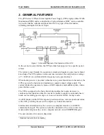
The batteries are always connected to the rectifier output and they supply voltage to
the inverter during power failures. During normal operation, the batteries are in
standby mode. The batteries for all models are housed in separate battery cabinets.
2.2.3 Inverter
The inverter receives a DC voltage from the charger or batteries and supplies a
regulated, frequency-stabilized, AC voltage (power). The inverter incorporates an
IGBT transistorized bridge, driver, (PC968 board), an L-C filter circuit, isolated
output transformer circuit, current transformer, PC906 board, and a PC801 control
board.
2.2.4 Static
Switch
In case the inverter cannot supply the load with the correct voltage (for example:
because of overload, inrush current on connecting the load, inverter malfunction,
etc.), the ST.SW/Bypass automatically transfers the load from the inverter to the
mains without voltage interruption or disturbance. When the UPS is in BYPASS
mode, the load draws power directly from the mains, bypassing the inverter. The
ST.SW automatically switches the load back to the inverter when inverter's output
voltage returns to normal.
The inverter is synchronized with the mains in both frequency and phase to ensure
correct operation of the static switch. The static switch includes the PC690 board and
the RA101 - RA103 contactors.
2.2.5
Bypass Isolation Transformer (option)
For customers requesting this option, the UPS includes an isolation transformer
connected to the Bypass AC input. The function of this transformer, together with the
Inverter isolation transformer, is to create a condition of complete galvanic isolation
between the input and output of the UPS.
2.2.6 Control
System
The control system performs the following functions:
•
Tests input, bypass, inverter, battery voltage, output current,
input/output signal frequency, and temperature.
•
Controls the inverter and the bypass changeover contactor—RA101—
and manages the static switch and charger voltage during battery tests.
•
Controls the Alarm interface.
•
Reads the panel keyboard and sends messages to the front panel LCD
display.
Summary of Contents for PS-SP Series
Page 1: ......


